Easily engineer trusses outside of Revit®
Everest is the first standalone product to create and analyze wood and metal trusses outside of the Revit® and MWF environment. Virtually any truss shape can be created in Everest by the automated profile creation or by manually drafting the envelopes. All trusses can then be analyzed according to AISI 2016 standards and ASCE 7-10 codes. Back to back and truss analysis and design wall truss configurations are both supported allowing users to design freely.
We’ll cover:
1. Truss Engineering Presets
2. Truss Analysis and Design
3. Engineered Truss Reports
1. Truss Engineering Presets:
Customize member sizes, webbing, and load settings in the Presets.
General: At this time AISI 2016 is supported.
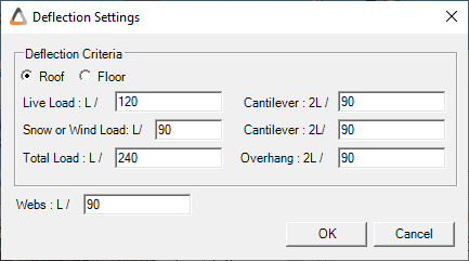
Deflection: The Deflection tab allows you to input deflection limits for Live Load, Total Load Cantilever, Overhang, and Webs.
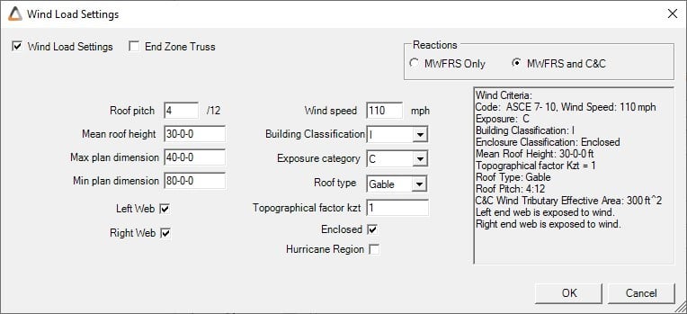
Wind:
DeflectionThe Wind tab allows users to customize the Wind Load Settings or turn off the Wind Load completely. The Roof Pitch, Mean Roof Height, Max. and Min. Plan Dimension, Wind Speed, and the Topographical Factor can be customized and by default are set to the values below. Exposure Category, Building Classification and Roof Type can also be customized according the code ASCE 7-10. Users are also given the option to include Components and Cladding (C&C) or strictly keep it an MWFRS.
Snow:
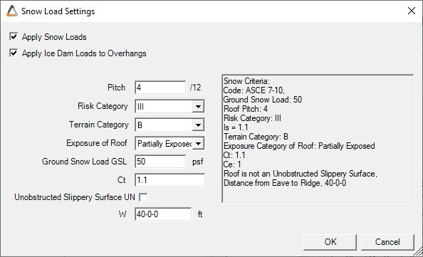
The Snow tab allows users to customize the Snow Load Settings or turn off the Snow Load completely by unselecting Apply Snow Loads. The Pitch, Ground Snow Load, Thermal Factor (Ct), and Distance from Eave to Ridge (W) can be customized and by default are set to the values shown below. Risk Category, Terrain Category, and Exposure can also be customized according the code ASCE 7-10.
Combinations
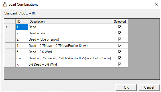
The Combinations window shows the possible different Load Combinations taken when performing analysis according to ASCE 7-10.
2. Truss analysis and design:
In the Truss Designer, the Engineering tab enables you to Display Loads and Analyze and Design the truss. Once analysis has passed, the structural Diagrams can be viewed.
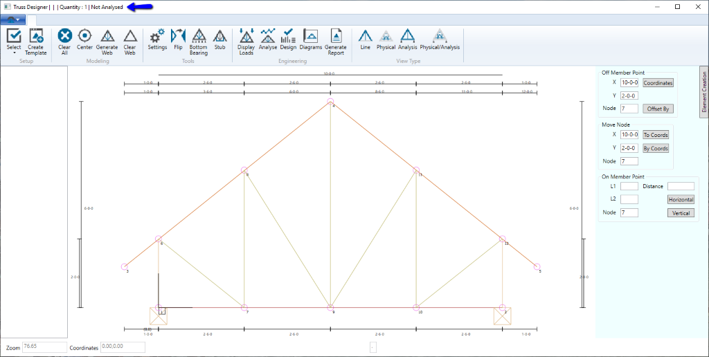
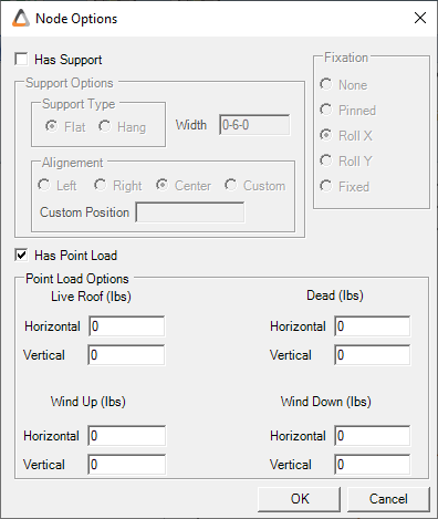
Node Options:
In the Truss Designer, you have the option to create point loads specific to a single truss (say roof trusses) with negative and positive Horizontal and Vertical loads.
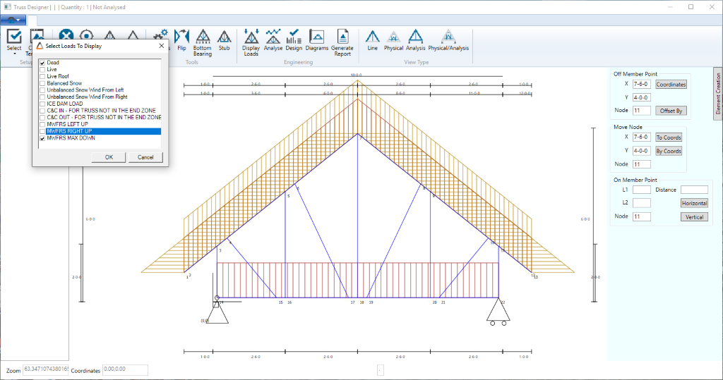
Display Loads:
Selecting Display Loads will bring the truss into the Analysis View. A dialogue box will pop up allowing you to select multiple types of distributed and point loads:
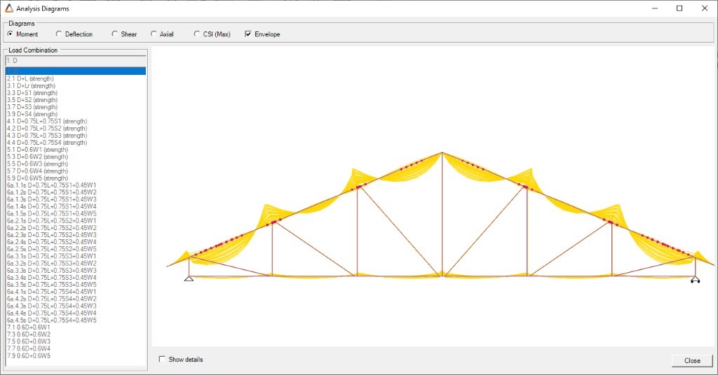
Diagrams:
View the analysis diagrams for all possible loading combinations. The Diagrams option displays multiple analysis diagrams under different load combinations for Moment, Deflection, Shear, Axial, and CSI. For example when Envelope is selected it shows all the possible bending moment diagrams.
3. Engineered Truss Reports:
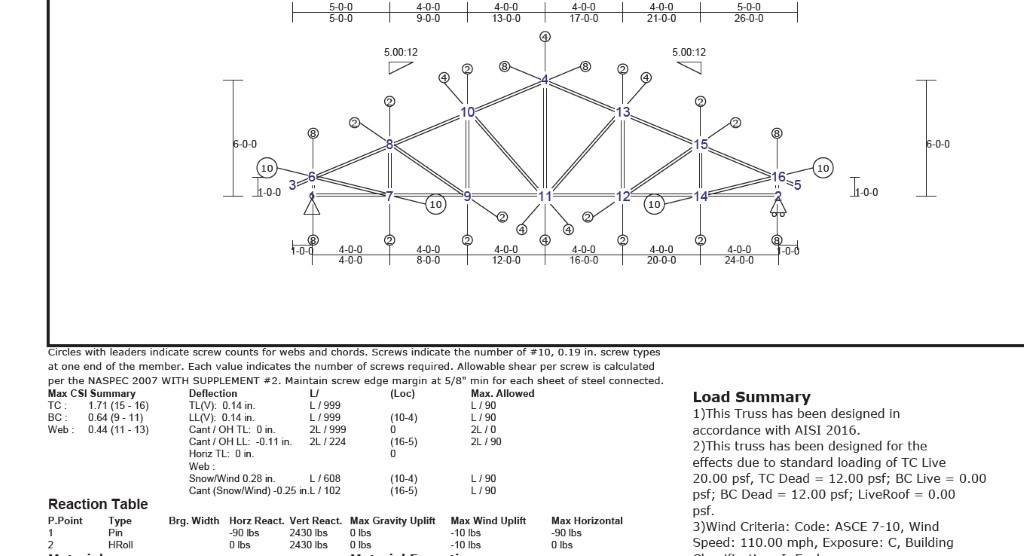
After a passed truss analysis, select Reports to produce a Fabrication Drawing, Engineering Drawing, and Detailed Engineering Drawing.
- Fabrication Drawings: provides the number of screws required for a specific location, the type, and an overall Total Screw Count. It also lists the separate members, their Length and Material.
- Engineering Drawings: provides a Reaction Table detailing the support reactions, as well as a Member Forces Summary and a Load Summary based on the loads and settings chosen in the Engineering Presets.
- Detailed Engineering Drawings: provides similar tables, but details the reactions of each member and joint.
For more information on Everest, take a look at the step-by-step video below :
For more information on our products and/or services, visit strucsoftsolutions.com, email us at info@strucsoftsolutions.com or call us at 514-538-6862.