Skip to content

Strucsoft’s New Release for Revit 2026 – Version 2.43, Build 9613

Table of Contents

Get started with your free trial now

Automate design and fabrication with the industry's most comprehensive Revit® framing software.

Strucsoft’s release in January 2026 introduced a major shift in how it handles panel creation  along with the Properties Preview window, Wall Analysis, and a significant cleanup of legacy tools.

Our second release this year (Version 2.43, Build 9613) picks up where that left off: refining the new workflow, filling in gaps, and adding long-requested capabilities like Custom Components and precise hole suppression.

Download it today by heading to your client portal.

Create Tool Update & New Workflow

The newly updated Create Tool introduces a unified workflow for creating wall panels, resulting in reduced setting time and ensuring that panels are generated accurately from the start.

The new workflow merges the steps for generating Standard panels (structural layer only) and Multilayer panels (panels with sheathing or secondary elements) into a single process.

Panels generated through the Create Tool are not classified as Multilayer by default – however, sheathing or secondary templates can be added at any time, provided the corresponding layers are available in the Revit wall.

Workflow: How the New Create Tool Works

  1. Panel Selection: Using the Create button, select a Revit wall and generate panels using either a default template or one you’ve configured yourself.
  2. The selected Revit wall(s) appear at the top left of the window, along with their available layers. The structural template is assigned to the Structure wall layer by default — specifically, the Default Wood Template for Strucsoft Wood, and the LGS Default Template for Strucsoft Metal, Strucsoft Metal+, and Strucsoft Suite. 

  3. All Panels and Panel Change These options become available once panels have been created and are accessed through Properties. They are disabled in the initial window that appears after clicking Create.
  4. Template Click the Template button to open the Template Manager, where you can assign an existing template to each available wall layer. If no additional templates are assigned, only the structural layer will be generated by default.
  5. Panel Settings At the top of the window, a preview of the selected Revit wall is shown alongside information about the currently selected layer. For Substrate and Finish layers, the settings type can be toggled between Secondary and Sheathing — available options update automatically based on the selection. For the Structural layer, only Structural settings apply; Secondary and Sheathing options cannot be assigned to a structural layer.

Note: When a Secondary or Sheathing template is assigned, the wall layer is automatically locked. To make instance-level modifications, unlock the layer and navigate to the Features tab.

Default Templates and Layer Management

  • Secondary and Sheathing templates are both supported for Finish and Substrate layers
  • Substrate and Finish layers are set to None by default. Templates can be assigned to these layers before creating the panel.

Template Assignment

  • Use the Template button to open the Template Manager and assign existing templates per layer.
  • The panel will the use the Default Structural template if a Template has not been assigned.

Modify Structural Templates from Template Map

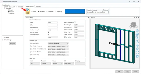
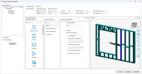
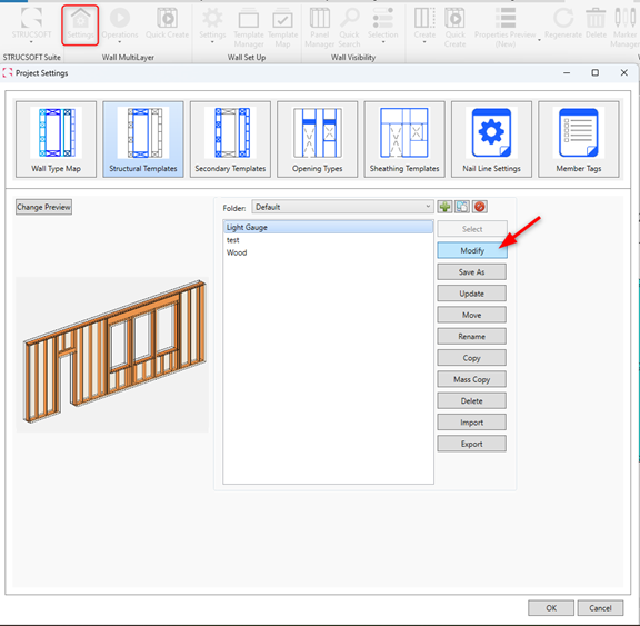
 Modify Structural Templates directly from the Multilayer Template Map, without needing to create a sample panel in Revit.

Re-organized Layout

In this release, the following features have had their settings windows reorganized to better align with the new panel Properties window: 

  • Horizontals
  • Hole Series
  • Extra Studs

Custom Components

Custom Components let you build non-standard panel elements directly in Revit using familiar Revit commands, then attach them to your panels through the new Add Custom Component tool.

Once created, a component can be reused across other panels in the project by assigning it to Marker Lines, without the need to rebuild it each time.

Creating a Custom Component

Start by modeling the component in Revit using standard Revit commands. Only supported family types will work: at this time, that means any line-based family within the Structural Framing Revit category. Support for point-based families is planned for the next release.

Once the component is modeled in the correct location, select all the elements that belong to it, then go to Tools > Create/Update Panel Component to register it with the panel.

After selecting the elements and choosing the panel they should be added to, a configuration window will automatically appear. Configure your component settings as needed, then click OK to save it to the panel.

The Custom Component members are then added to the Strucsoft panel. To confirm the component has been registered correctly, check the Strucsoft parameters now attached to the members — these indicate the elements are recognized as part of the panel. Here is an example of parameters to look for:


Adding an Existing Custom Component to Other Panels

Once a Custom Component has been created, it can be reused across any panel in the project:

  1. Select the panel you want to add the component to.
  2. Go to Markers > Create Marker Lines.
  3. Choose the correct tab (Horizontal or Vertical) based on how the Custom Component was originally saved.
  4. Set the number of lines and the spacing between them (if applicable), then select the Custom Component from the dropdown menu.
  5. Click OK and regenerate the panel to see the Custom Components in place.

Note: Custom Components saved as Horizontal will only appear in the Horizontal tab, and vice versa for Vertical.

Adjusting and Removing Custom Components

Marker Lines can now be moved laterally for justification adjustments, and their length and position can be modified freely within the panel. To remove a Custom Component entirely, delete the associated Marker Lines and regenerate the panel.

Suppress Holes at Specific Offsets in Wall Panels

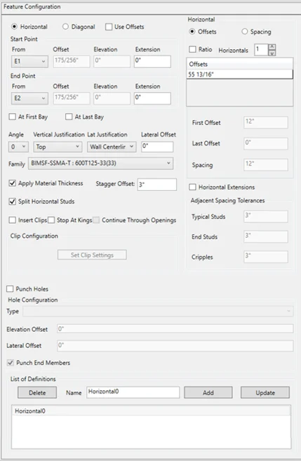
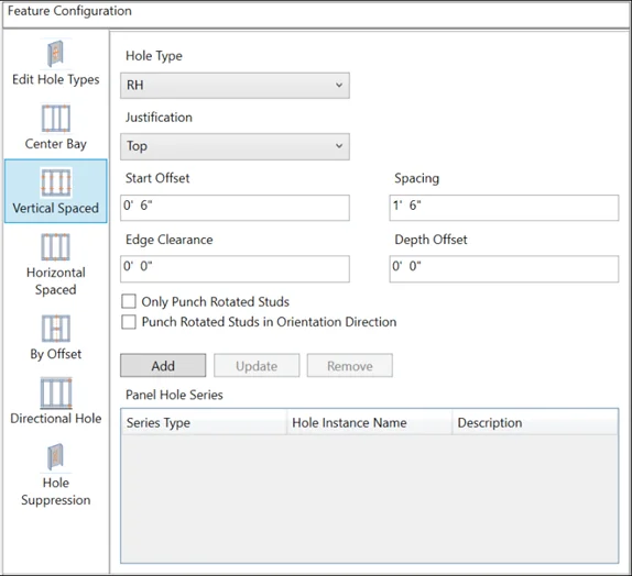
You can now suppress punches at specific locations on a wall panel while preserving the rest of the punch and service-hole pattern across the panel. This gives you precise control over where holes are, and aren’t, without having to disable the full pattern.

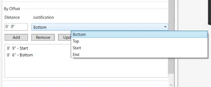
For added flexibility, a reference point can be defined to specify the distance at which holes should not be placed. The reference point can be set to the start, end, top, or bottom of the panel, and multiple suppression regions can be applied to a single panel.

Assign Specific Family Types to Nailers in Wood Opening Markers

A new field is now available in Wood Opening Markers that lets you assign a specific family type to Nailers, rather than inheriting the Panel Track family by default.

The Nailer field defaults to “same as Panel Track,” but you can select any other family type from the dropdown menu at any time. Just make sure the desired family type is loaded into your Revit project before selecting it.

Extra Studs: Repeat/Modify Now Supports Header Members

Header members can now be modified by using Extra Studs – Repeat/Modify options. Furthermore, users can add new members, change family types, and the header will be updated accordingly. 

Introducing New Parameters: Panel Length and Panel Height

New parameters are now available in the panel’s label:

  • BIMSF_PanelLength
  • BIMSF_PanelHeight

Both parameters represent the actual length and height of the Strucsoft panel and can be pulled directly into Revit schedules — giving you accurate panel dimensions without manual measurement or workarounds.

Floor Truss Improvements

Floor panels created with Floor Truss templates now support two capabilities that were previously limited to standard Joist Floor panels: Sheathing and full-panel Shop Drawing generation.

Sheathing

Sheathing is now available for Floor Truss panels, using the same tool you’d use on regular Joist Floors.

Shop Drawings

The Floors Shop Drawings engine now supports Floor Truss panels and will generate drawings for the entire panel in a single pass. Shop drawings for the Truss module can also be used to generate individual drawings for each truss.

Shop Drawings - Standard and Multilayer Tabs Merged

In line with the updated wall panel creation workflow, the separate Standard and Multilayer tabs have been removed from the Shop Drawings engine. The tool now automatically recognizes any panel, whether existing or newly created, and presents a unified interface.

You can continue to add as many sheets as needed to cover specific technical drawings for structural layers or secondary and finish layers.

Box Header Members from Multisystem Marker Now Supported By Bearing Cutback Options

Bearing cutback options now support Box header configurations assigned to panels with Multisystem Markers

New TrimJoist Families Available in Strucsoft Suite and Strucsoft Wood

Through a new collaboration with TrimJoist, open web joist families are now available for wood floors and ceilings within Strucsoft

All available TrimJoist depths and lengths can be found in the Strucsoft Library, accessible from the Download Center or through Revit’s Load Family command. Families are located in the Strucsoft installer folder under Floor Families > Imperial > Manufacturers.

Select the appropriate length for your floor configuration and use the open web structure to coordinate Mep routing accurately within your projects.

Adjust how edges should be trimmed and correct placement of the joists by manipulating the following parameters once families are generated in the panel: 

Adjust how edges should be trimmed and correct placement of the joists by manipulating the following parameters once families are generated in the panel: 

The 2026.2 release is available now through your client portal. We’d love to hear how these updates fit into your workflow. Share your feedback or request new features through Graitec Advantage, and stay tuned for what’s coming next.

Articles You May be Interested In

5 FAQs about Offsite Construction

Offsite construction rests on two pillars: design, and manufacturing. Between those two pillars is the data flow, that connects them. The smooth flow of accurate data is what closes the gap between the design team, and the manufacturing team on the shop floor.  

Read Article

Some of our international clients that use our software

Sign up for a free demo

Our experts will walk you through:

How to implement Strucsoft into your existing project life cycle.

How to navigate around the Revit® and Strucsoft user interfaces.

How to access training material such as guides, e-books and the help center.

Get started

Before you go!
Stay in the know.

In a hurry? Sign up to our newsletter and stay on top of the latest news and insights from the industry’s leading developer of Revit framing software. Sign up today!