Simplify Floor Engineering with Strucsoft for Revit
Date
Duration
Speaker

Thais Blinovas
Product Manager - Strucsoft
Watch the recording
What’s the webinar about?
Join us for a comprehensive webinar on floor engineering with Strucsoft Wood, a leading Revit framing plugin. Discover how our plugins integrate with powerful material sizing tools like Forte by Weyerhaeuser and Sizer by Woodworks, enabling you to size and engineer floor systems and beams directly within the Revit environment. Discover the tools that automate your design process, simplify coordination and streamline fabrication with automated shop drawings and easy CNC output.
What you’ll learn
- Splitting Revit floors into panels using the MWF Floor Cutter for analysis and off-site fabrication.
- Framing wood floors in Strucsoft: joist direction, spacing, templates, and adding rim/joist-supported openings.
- Key Strucsoft features that power DBRunning BC Calc floor analysis in Revit 2025
- Generating shop drawings: identical member labeling, custom sheet layouts, dimensions, and cutting lists.
Read the full video transcript
*Please note that MWF has been rebranded to Strucsoft
Hi, I’ll be delivering a short webinar on floor engineering and structure of wood framing in Revit. We have a number of these webinars coming up, so if you’d like to register for those, scan the code on the screen or go to the web address shown to view the calendar. All sessions are recorded, so you can always go back and watch them later.
My name is Steve Crow, and I work for the Graitec group. As you can see, I’m based in the UK. I’ve been with Graitec since January 1989—so that’s 36 years now. I cover training and support for AutoCAD, Revit Architecture, MEP, and I’ve recently taken on the Strucsoft framing software. In my spare time, I ride a motorbike, do DIY projects, and I’ve been a beekeeper for quite a few years. Nothing I enjoy more than getting out walking on the hills with my lad—we even covered Ben Nevis last year.
Today, we’re looking at floor framing in Revit. I’m not going to cover how to create floors—that would be in a separate webinar—so I’m assuming you can create floors and the walls to support them. We’ll look at splitting floors, adding openings in various ways, framing those floors (very similar to framing walls), running floor analysis using the BC Calc engine, reviewing the analysis output, designing the members, creating shop drawings, and then opening it up for Q&A. If we can’t answer questions live, we’ll take your details and get back to you.
My email address is on screen for any follow-up questions. Feel free to scan the code for the calendar of upcoming and past events to access recordings.
Let’s dive in. Here we have a floor supported by walls, including some internal ones. Switching to top view and spinning it around—I’m running Revit 2025.
We’ll split the floor into manageable panels for off-site manufacturing or analysis. You can split floors in Revit, but I’ll show how to do it using the MWF tools from Strucsoft. There’s a Floor Cutter tool.
First, draw model lines on the floor where you want splits. Go to the Architecture tab, Model Lines. To see better, I set transparency on the floor: right-click, Override Graphics in View > By Element, set transparency to 60 so walls show through for alignment.
I’ll create three separate floors. Draw model lines in the middle of walls, extending beyond. Select the floor and model line(s), go to the MWF Pro ribbon > Floor module > Floor Cutter tool. Pick the floor and line, then cut. It prompts to delete the original floor—say yes—and keep the same timber floor type.
Repeat for the other sections. Now we have three separate floors. Delete or hide the model lines. Add transparency to all three floors for visibility.
That was using the Floor Cutter to create separate panels—you could have done it natively in Revit too.
For framing with the MWF Strucsoft software, ensure floors are supported (by walls or beams). In 3D, you can see oversailing on external walls or support by beams underneath—that’s considered in analysis.
Select a floor, go to Strucsoft > Create. It’s similar to wall panels. You can select a template if assigned to the floor type—it frames all matching floors. Otherwise, pick one manually (mapping is similar to walls).
Create places markers at corners showing panel extents and name. Regenerate to insert timbers. Repeat for others—Quick Create and Regenerate buttons speed it up.
Framing appears. Green icon shows joist direction; red shows panel direction (labeling from bottom: Joist 1, 2, etc.).
To change direction: select panel/label/beam, go to properties > Member Properties > Joists > set angle (e.g., 90 degrees) and OK—it rejigs.
Change spacing in properties (e.g., 300 mm). Member sizes don’t matter yet—analysis determines required sizes based on loads. Position is key.
Apply templates for consistency (e.g., “Template 39 – 300 centers”). Update properties and apply—much quicker with pre-set templates and mapping (frame multiple floors at once).
Now, openings. You can add them in Revit (Architecture > Opening > Vertical, or edit profile). But use the Opening Manager in MWF Pro.
Draw model lines for the opening shape (e.g., rectangle on faces). Select lines, go to MWF Pro > Tools > Create an Opening. It knows the panel and creates an opening marker and hole.
Update profile on the panel—it recognizes the hole. Warnings about coincident markers (overlapping outlines) are common—just OK.
Set opening type (e.g., rim supported adds full joist; joist supported extends trimmers). Regenerate—opening framed.
To modify: select marker, recreate opening, change type, update profile, regenerate.
To remove: select marker > Delete tool, update profile, regenerate—opening gone.
We’ve framed openings nicely in 3D.
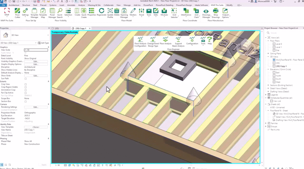
Next: analysis. Select a panel (e.g., Floor Panel 23). On the ribbon: Floor Engineer panel > Floor Analysis Configuration.
Engine is BC Calc (in Revit 2025+; earlier versions had BC Calc, Wood Forte, WoodWorks Sizer—they work similarly).
Set building codes, manufacturers’ joists (edit presets, tick available ones), loading configurations (live loads, wind, deflections—create defaults or custom for internal/external floors).
Apply design type to panel (Change Panel Design Type > select configuration).
Analyze Selected Panel—it processes beams around openings, lists products/groups (trimmers, headers, etc.).
Use best analysis, apply to all groups (consistent sizing), OK. Results show passing products; select one (e.g., wood web joist), replace all members. Close and save results.
In 3D, see uniform members. Summary table shows supports (B1/B2), loads, deflections, reactions, shear—reports per group (long joists, trimmers, headers). Print as PDF for job.
We’ve framed, added openings, run analysis, sized members.
Finally: shop drawings. Ribbon: Floor Manufacturer panel > Drawing Manager (settings/templates for sheets, views, text/dimension styles, placement zones, scales, rotations for fit, visible categories like ducts/pipes for coordination).
Add Schedule Label first—finds identical members (e.g., all same joists get J0 instead of individual instance labels).
Refresh drawings to update. Override Hidden shows hidden elements (e.g., risers through openings).
Generate Shop Drawings—creates sheet automatically (views, dimensions, cutting list grouped by label/count/length, brackets/hangers).
Example: Floor Panel 23 sheet at 1:25 or 1:50 scale—plan, 3D, dimensions (bottom, right, diagonals), cutting list.
Adjust headings, scales, etc., in settings (detailed in training; Graitec can create custom settings for you).
Q&A
Some previous questions:
Can you add point loads or additional line loads? Yes, on joists.
Can you add hangers? Yes, but analysis currently works only on rectangular lumber. For plywood web/lattice joists, add in Revit, not analysis.
Does analysis work for open web joists? Not yet—limited to lumber/products in BC Calc.
If you have questions in chat, we’ll answer live or follow up.
Thank you very much—hope you enjoyed it. Enjoy the rest of your day!
Some of our international clients that use our software