Simplify Detailing and Documentation with Strucsoft for Revit
Date
Duration
Speaker

Michael James
Technical Solutions Specialist
Watch the recording
What’s the webinar about?
Find out how to create automated detailing and documentation for your modular construction projects with Strucsoft for Revit. Dive into essential topics like preparing your Revit model for modular framing by grouping walls, configuring templates, and generating template maps for seamless automation. Learn how to use single-layer tools to frame modules quickly, copy framing properties across identical groups, and maintain consistency with locking features. Whether you’re framing with multi-layer panels for sheathing and secondary layers or applying join and split markers, this session demonstrates how Strucsoft streamlines the process, saving time while ensuring accuracy across your projects.
Perfect for architects and engineers working on modular construction, this webinar equips you with practical steps to enhance your Revit framing workflow.
What you’ll learn
- Prepare Revit models for modular framing by using model groups for modular units, configuring framing templates, generating template maps for automated wall assignment, and placing join/split markers for consistent panel definition.
- Frame single-layer modular units efficiently using Strucsoft's modular tools: apply Quick Create with active template maps, then copy panel properties/members to identical groups (with options for numbering, locking child panels to parents, and maintaining consistency).
- Manage multi-layer modular framing (including sheathing, gypsum, and ply boards) by using dedicated multi-layer operations and copy tools to propagate framing and secondary layers across identical modules while preserving accuracy.
- Generate consolidated modular documentation via the Gather Sheets feature: create single sheets displaying all panels from a module (plan + elevations + schedules), customize view settings (scale, orientation, dimensions, labels, BOMs), and produce aligned, fabrication-ready shop drawings with hardware quantities and cut lists.
Read the full video transcript
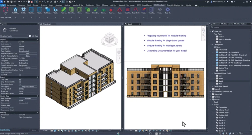
Hi everyone, my name is Michael James and welcome to my webinar. Today we’re going to take a look at how we can unlock modular documentation and detailing with Strucsoft for Revit. During this webinar I will cover the following topics: preparing your model for modular framing, modular framing using the single layer tools, modular framing when using the multi-layer tools, and generating documentation for your modules using the modular gather sheets feature. The modular features allow users to frame matching model elements quickly whilst maintaining consistency and accuracy in the models. The modular features add an extra layer of automation by allowing users to frame multiple modules in just a few clicks.
To start framing using the modular tools, there are a few things you’ll need to consider when preparing your model for framing. I’ll open up my floor plan where you can see my modules on the left and the model on the now my floor plan; you’ll see on the hand side my floor plan is made up of these modular units, and as I hover over the units you’ll see this dotted blue line which leads me on to point one when we’re preparing our model for framing using the modular tools. Point one is that we want to make sure that all of the walls that make up the module are part of a model group. The reason for this is we can frame all of these elements in a few clicks all at the same time and they’ll all be associated with the module. The next thing that we need to make sure we have prepared before we create our framing in the modular unit is to configure our framing templates. Configuring framing templates is standard practice and this is something that we usually do anyway when we want to apply the same settings elsewhere in a project. For step 3 we need to make sure that we generate template maps. Template maps allow us to automate the process of applying our templates to our Revit walls and this is the quickest way to apply your framing to your wall elements. If you have to specify your join configurations for your walls in your modules then I would advise that you place joins join markers as you can place joins before you frame; you can also place them after you’ve placed your framing elements as but placing joins will allow you to define your modules and frame them consistently throughout your project. And then lastly if you need to split your panels into smaller panels then you can place split markers to define where panels should start and end. It’s best to place these outside of the model group where you can then delete them and add additional ones as necessary.
Now I’m going to go through the process of how we can frame our modules using the single layer framing modular tools. As you can see within the Strucsoft (formerly MWF) menu we have a dedicated toolset for the modular framing. Within this menu we have a range of tools that we can use in order to aid us with framing our modular units. Before I want to explore these tools I need to frame one of these modular groups; we can explore some of the tools. I’m going to do is I’m going to select this modular unit and within Strucsoft (formerly MWF) I’m going to click on my template map first of all just to ensure that this is active and I’m also going to click the quick create button in order to start framing the panels within this module. As we’re framing these walls within this module it’s going to frame each one according to the template assigned to each wall type. We don’t have to worry about the panels being placed correctly because it’s all based on the template that’s been assigned to that wall type. Once complete you’ll see that we have our panels placed within this modular unit. What I need to do now is I need to apply these panel properties or the modular panels which are framed within this module; I need to apply these wherever these modules occur within my project. You can see there are a couple of areas where we have similar units; we have the r configuration here and we have one l configuration. Within our modular menu we have the ability to copy the framing from an existing module and apply it to other similar units or identical units. What I need to do first is select my module where I want to take the panel properties from. Go to the modular tool and click on copy members on all identical groups. Once I click on copy members on all identical groups I’ll see the modular settings where I can set the panel numbering. We have two options: we can continue the numbering if we have panel 1, 2, 3, 4, 5; we can continue 6, 7, 8, 9, 10 from there. Otherwise we can have the new panels take on the existing numbering from the existing module; each panel will have the same number based on the configuration being the same. Just for today I’m going to continue the numbering but we also have the option to label them or name them the same as original. Under parent settings we can set the original panels as the parent panels and we can also lock the child panels which are created from the parent panels. We can also lock those to the settings within the parent. We don’t have to lock these; we can simply uncheck them if you want to but for now I’ll show you what happens when we do lock them.
Now it’s detecting all the groups that are similar to what I have here at the moment and it’s going to frame them using the same settings. Now our module has been placed and our child panels have been framed; you can see that these panels are locked and once locked they have this red overlay just to let us know that these are now locked for editing. When we need more flexibility when selecting the groups to frame we have the option to copy members from selected groups rather than distribute the settings to all groups. In the modular menu we have a tool called copy members from group. This is based on selection rather than distribute all these settings to all groups at once; we can be specific about the groups that we want to apply the settings to. To demonstrate this tool I’m going to have to frame one of these other groups that are available. You can see we have the hand equivalent to unit b which has already been framed. I’m just going to quickly frame this one and now these panels are framed. What we need to do this time rather than select the group first and distribute the settings from this group to all the other identical groups what I can do now is I can click on the group that I want to frame. This one for example go into the modular menu and from there I can say copy members from group where it’s going to prompt me to select the group that I want to copy the properties from. I’m just going to select this group here and again we have the same menu that we’ve just seen not too long ago. From there I’m going to unlock the panels this time and I’m just going to click once complete; we can take a look at that framed group and you can see we’ve copied the properties from that selected group and we continued the numbering from the previous panels. You can see that it has framed these with the same settings.
As as copying members from panels we can also match properties on panels as to demonstrate this I will frame one of the other groups that are available. Once the frame is complete we just want to distribute the settings from this group to the other identical groups. I’m going to do is select this group first of all, go to Strucsoft (formerly MWF) and within the marginal menu I want to say copy members on all identical groups. This time rather than use the same panel numbering convention I’m going to set this to same as original and when I set it the same as original you’ll see there is a message here just to let us know that when we set the naming convention to same as original the alternate naming convention will take effect then our panels they’ll all share the same alternate name value. It’s also letting us know that the naming method will be automatically updated that will show us the alternate name value in the view. Click okay and I want to make sure I lock the panels. I’ll click once complete you’ll see that all of those groups which are matching and now framed accordingly using the same panel naming convention it’s panel 59 here and we have panel 59 from the original panel. If we take a look at the locked panels I’ll show you where we can see that alternate name value if I go into panel 61 for example I’m going to panel properties you’ll see within a general general info tab we have the alternate name value set to panel 61. The original panel name would have been different it would have been panel number 73 with the prefix panel this is where we can find the original panel number and you can see that this is the alternate name value which is currently displayed in the view.
If I were trying to make any changes to a locked panel this panel is locked to the parent this is a child panel from the parent panel if I wanted to make any changes to this panel I’ll get a warning to say that this panel is locked if I try and change the visibility of the panel label for example you’ll see that we are we have a warning here you are modifying a panel that is part of the group showing the same numbering this is based on showing the same numbering value would you to apply these changes to all instances we can change all of the groups they all have this change I’m about to make or we can make another panel instance we can make another instance of the group if not the panel label will be assigned a new number label I’ll say no at this point and I’ll also get the warning to say that panel 61 is locked and we have to unlock it before attempting to modify this panel as I said before this is locked to the parent we would make the changes via the parent in order for it to update yes I’m just going to say no to apply changes and what I’ll show you now is how we can make the changes to the parent and then apply those changes if necessary to the child panels we have much match properties on all identical groups let’s imagine the change I want to make here it’s going to affect all of these existing groups now within the parent group I’m going to make a change to one of the panels just we can see that change reflected in the other panels I’m going to do is I’m going to pick on panel 61 and I’m going to go into the panel properties here within the panel properties I want to make a simple change that we’ll see that we can see reflected across the panels in other areas I’m going to go to miscellaneous structural members I’m just going to change the stud configuration to add double studs for every single vertical we can see we will see double studs instead once I click you’ll see we have this message this pop-up just to tell us that we’re making the panels inconsistent we’re making a change to this panel which is different to the other panels from what Strucsoft (formerly MWF) can see you are modifying a panel that is part of a group sharing the same numbering would you to apply these changes to all instances within the group and if not the panel will be assigned a new number or label I will want to make this change across all the other panels and this is one way that we can apply those changes if you want to maintain consistency if we say yes we’ll apply the changes to all the other groups as then you’ll see that these changes that I’m about to play apply to panel 61 will also be applied to the other identical groups once complete we can see across our child panels or child modules we will see that change to panel 61 which now shows those double stud configurations as expected.
Now let’s imagine we want to make an instance change to one of these panels where we want to add some new members rather than make this change within the panel properties I want to make a change just an instance change to some of the members within panel 60 for example I’m going to do is select one of the members here we have s7 what I’m going to do is I’m simply going to copy these members and place them here we have a triple stud configuration not too far from the opening as you can see there I’m going to save these to the panel I’m going to go to edits once I’m going to add this simple change I now want to match these properties I want the other panels to reflect the changes that I’ve made to panel 60 I want them all to be consistent based on these new edits that I’ve made to panel 60 in the Strucsoft (formerly MWF) menu I can go to the modular tool and we can use the match properties on all identical groups option if I only wanted to match these on a selected group then we also have the match by selection option here as but in this case I want to match it on all groups again we can define the numbering convention and we can set these source panel as parent I’m going to keep these settings as they are and I’ll just click once complete we can check on the child groups just to make sure that this change has been applied you can see here for s7 we have these members configured around this area here now I’m going to go to panel 60 over here you’ll see I also have the triple stud members including s7 as shown here and also the other group as shown here.
If we would to delete any of our modelled groups or modular units we can delete the framing from within the modular units by using the options within the modular menu we have the option to delete members on all identical groups which will delete all of the members from all the groups otherwise we can delete by selection simply by selecting the group that we would to delete and using the same methods that we would usually use when deleting a panel then we can say delete choose the option that we would to apply and that will delete all of the panels in the model group when framing our multi-layer panels it’s important that we have our multi-layer template map generated when we go to frame our panels all the sheathing and any secondary layers are automatically placed as if I go to the wall multi-layer panel within my settings we’ll be able to see that our walls are configured to show our sheathing and other elements as necessary what I’m going to do is select unit c and I’m going to go into Strucsoft (formerly MWF) operations and hit quick create this unit will be framed using the multi-layer tools that means our sheathing boards our gypsum and ply boards are going to be placed as and once complete we’ll be able to view this in 3d where we can see our sheathing boards have been placed on our panels we have our gypsum boards on the interior and our ply boards placed on the exterior.
Now I want to apply the framing from my multi-layer panel to the multi-layer panels within my model rather than just use the modular tools and copy members from identical groups because all that’s going to result in is my framing being placed what I need to use is the modular tool from within our multi-layer panel or within our multi-layer menu first of all I’m going to select the group that I want to take the properties from I can distribute these to the other identical groups then in Strucsoft (formerly MWF) I’ll go to operations and at the bottom of the operations menu you’ll see that we have some similar options to those which were shown in the modular menu we have copy members to all identical groups and we have copy by selection as we can copy members from a group based on selecting the groups that we want to frame using the selected group I’m going to copy members and all identical groups again we have the option to choose our panel numbering we can choose the parent settings we can lock our panels and we can set the original panels as the parent panels I’m going to lock these and I’m going to use the continuing numbering naming convention I’ll click and now that’s done we can check the areas where these groups have been applied and if I want us to view these in 3d you’ll see that our sheathing boards have also been placed in our module using the copy tool from the multi-layer menu.
Once we’ve generated the elements for our single and multi-layer panels within our modules the only thing that’s left to do now is create our shop drawings rather than generate drawings for multiple panels across separate sheets relating to the module what I want to use is the gather sheets feature this is going to allow me to create a single sheet which will show all of the panels belonging to a particular module I can say for module c show me the exterior walls and also show me the interior walls that make up module c we can have them all shown on one sheet in a single representation we’ll find this tool within the single layer modular menu if I go to modular you’ll see at the bottom of the list we have modular gather sheets once I select modular gather sheets it will take me into this dialog box where you can see that we have various options that allow us to configure our views for our gather sheet in our general tab we have some drawing settings where we can save our configuration at the moment we’ve got add we can create a new configuration we can save our settings we can use them again at a later stage we can also export these to another project if we need to use them in another project elsewhere I’m just going to call these ones webinar and beneath the drawing settings this is where we can start to set up how our views are meant to appear on the sheet for our view scale we can define our view scale this will affect all the drawings on the sheet each view will be placed on the sheet at the scale that is defined viewport type we’ll have title with line although we also have a few other options here as title block we can define which sheet we’re going to use depending on the sheet sizes available you may need to load in additional sizes or you can utilize one of the ones that are already loaded into your project we can define our view orientation we have interior to exterior we’re going to view the panels from the interior looking through to the exterior side or we have exterior to interior or we’re viewing the panels from the exterior looking through to the interior side we have by panel direction if you have modified the panel direction to say rather than starting from left when looking from interior you’re looking from left when looking from the exterior side then this will define the orientation of the panel instead and you’ve also got by marker direction as if you place a top side marker we can also use the top side marker to define the orientation of the panels.
Sheet number this is the number that is going to show up in the sheets when we create our sheets we’ll see the sheet number and we’ll see the sheet name as based on the representation that we place here if I just take away gather and just put modular sheets then once we generate our sheets we’ll see the word modular sheets and modular panels as the sheet name on the bottom left we have sheet margins if you need to add a margin from the top of your sheet we can define a margin value there we can add a margin at the bottom left and hand side if necessary this is based on your project units if you type in for example if you’re working in imperial and you’re working in inches if you type in one it will be one inch if it’s feet if you type in one it will be one foot for example on the hand side we’ve got groups and this is based on any model groups that we have available in the view or in the project at the moment at the moment in our view we have the chase walls external door l we’ve got a few different groups that we can choose from I already know that we have a couple of groups predefined already or which have already already been framed I’m going to use unit c l the left representation of unit c which has been framed using the multi-layer features if we want to use the schedule label value we can run distribution before we generate our drawings if you haven’t generated your schedule label values you can run distribution as we create those sheets and each panel will be given the appropriate schedule label delete existing gather sheets will allow us to override any older sheets with the newer settings if we want to recreate our sheets this will be checked on automatically.
In the next tab we have the module plan view this is where we can define how our panels are going to be displayed when they’re shown in plan view first we can define a view template if we have generated a view template for our framing to show in a certain way we can apply that to our modular gather sheets that our plan view in this case can show according to the template settings this is a list of all of our Revit templates where we can define any of the view templates that we have set up for our shop drawings view detail we want to show this in at least a fine level of detail we can see all of the physical representations for our panel members visual style we have the choice of defining hidden line shading shading with edges and wireframe I’m just going to set this to hidden line for now we can define our dimensions and based on the dimension styles available in our project we can redefine our dimension styles if necessary we have the same options for panel lengths where again we can define the dimension style and we have the same options for openings as if we want to dimension our openings call out tag this will allow you to apply a call out a dwg if you have one defined in your project you can then map this to your gather sheets as and define it here in this area view cut plane as we’re showing our view in plan we can define a bottom extent for our drawing and a top extent to say we want to see between 0 and 1200 we’re going to see 1.2 meters above that zero point which is defined for our far clip offset if we wanted to see further down then I believe we could set this value to a minus figure in which case it’s going to be offset below that zero point in our view we have some view specific options which will allow us to manipulate the view orientation we have none which will not change the view in any way once we place our plan view it’s going to place it on the sheet without any influence from us group rotation check for longest member based on the longest member if your plan view is a narrow plan view or it’s a narrow module you may want the longest members to be turned on their side they fit nicely on the landscape sheet for example in this case we can rotate the views clockwise or anti-clockwise and I’m just going to define these to rotate based on the longest member to make sure that these are showing clockwise we also have the option to rotate based on shortest member and again we have to rotate clockwise and rotate counterclockwise options there.
For our elevation views again we can define the appearance of our elevations for our panels which are shown in elevation we can define the template if we have one we can define the view detail again we want this set to a fine level of detail and for visual style we can set this either a shaded hidden line shaded with edges and wireframe after that we have the layer selection just in our shop drawings these are telling us that these settings will only apply to multi-layer panels for a single layer panel it’s going to take our structural layer and by default but when we have a multi-layer panel we can define the other elements that we want to show in relation to the framing elements as as structure maybe I want to see finish one which will be the elements on the exterior side if I’m looking from interior to exterior then I’ll be able to see the sheathing behind the framing members not in front of the framing members but maybe I’d want to see those in front of the framing members in which case I could change the orientation of the view and manipulate that if I wanted to for now I’m going to set these to finish one and just make sure that we are looking from interior to exterior next we’ve got the horizontal dimension type let me just uncheck this one next we have horizontal dim type where if we want to place any horizontal dimensions we can define our dimension style for that otherwise if it’s set to none it will not place a dimension for this particular dimension headers and sills we can dimension those as we can define the total panel height if I wanted to show the total panel height maybe I want to define this using my sample shop drawings dimension stud dimension type we can dimension from stud to stud and again if I wanted to show this we can also show this in using the dimension style of our choice there are many different things we can dimension as you can see we’ve got kings total panel length opening size and this is particularly for our elevation views even though we have configured these for our plan view if we want to show these in elevation as this is where we can define to show that opening size if you want to show openings we can also show those it may be more useful to see these in elevation than in plan because in this way we can see the width and the height of the opening let me just change this to three and a half mil connecting panels text note we can also show a note to say which panels that this panels that this panels is connected to we could see panel one in the middle for example and on the left it’s connected to panel three on the it’s connected to panel six for example infill header if we have an infill header configuration we can also dimension that or we can show a text note for that label jam multi-system if we’ve got a multi-system jam configuration or a built up jam configuration we can also show show that with a text note as we can define that our elevation views will align to plan view once we place our panels in plan we want our elevation drawings or elevation views to also align to the plan views we can see those nice and clearly and reference where they’re from we can display the levels as if we wanted to see the bottom level of the panel and the top level where it terminates we can see those in the view as and this will be placed for every elevation you may not want to see it for every elevation but in this case it will place one for every elevation.
And labels in the labels tab this is where we can define how we want to label the members are we going to label them based on their panel name or are we going to label sorry the member name sorry or are we going to label each one based on the schedule label we can show all of the members based on them sharing the same characteristics same lengths same member types in this case I’m going to say schedule label by schedule label we can define how we want to label these members do we want to label all of the members or we can choose by selection in which case on the hand side this is where we can define the members we want to label label alignment we’re going to place our labels in the center of the members we can also define to place them on the left above or below label orientation we want to make sure that this is consistently readable but if you don’t you can also change your orientation to vertical but we’ve got horizontal and vertical as the options available and for the text node type when we’re placing our text which type of text do we want to use we can define that from here again based on all of the text styles available in your project when there are members which are in close proximity which share the same or common values you can group those with a number in brackets to say that if there are two c0 members two vertical members very close together rather than show c0 twice we can say c0 c0 and in brackets have the number two to say there are two members in close proximity otherwise you can mem label the members along their sides and you could also choose not to group do not group if they are in close proximity.
And then finally for our bill of materials if we want to quantify the members and show some information based on the cut length and the weight these values then this is where we can do it in the bill of materials layer selection this will only apply to multi-layer panels if we are working with single layer panels then we can essentially ignore this section here but this is where we can define the layers if we are working with a multi-layer panel maybe I want to show the sheathing on the exterior side and I want to reference the structural members as if the elements are unchecked it will not reference those elements in the panel in the bill of materials we’ve got show title and panel counts if positioned if we wanted to show the title above above each of these bill of materials schedules we can show a title which is going to reference the panel name we can itemize every instance which means each row of data is going to be each row of data is going to be positioned on its own row or each piece of data is going to be positioned on its own row and then we’ve got title we can define how we want to show the title text the column header text and the column body text as again we can define these or change these based on the textiles that are available in the project to quantity it’s also given us information based on the type of parameter that this is in in this case for count it’s an integer for our reported length it is a text value here we’ve got schedule label which again is text and master container which is shown as text we can define the alignment of all of our text values as all of our parameters and where it says width we can auto calculate the size of the column based on the text that is placed within each column this will allow you to resize the table it’s not too big and some of the values aren’t showing that’s too wide in the Revit schedule if you have an existing schedule that you want to copy or use the same characteristics from that table then you can use the duplicate existing schedule option and this will allow you to select a schedule from some of the predefined schedules or schedules that you may have made at an earlier stage if you would to save your settings settings then just make sure you give your settings a name and if you make any changes to your settings you can simply say update and the new changes that you’ve made to your settings will then be saved back to your configuration as mentioned previously you can export these to another project if you need to and you can import them you can use them in a project if there are no settings predefined.
For now I’ll click and we’ll see how our sheets will look once the gather sheets process is complete we can take a look at the sheets if we go down to the sheet section here you’ll see we have modular sheet unit c and then we have modular panels which is the panel number that was shown in the gather sheet settings we have two sheets which are generated we have a model related elements we’ve got our plan view elevation of our panels all belonging to this modular unit and then we’ll have our schedules which are placed on a separate sheet just because they can’t fit on the the main sheet with all of the physical elements we’ll see a second sheet referencing all of the panels from the modular unit first let’s take a look at the physical panels you’ll notice it places our elevations in alignment with our plan view as we requested in the settings we have dimensions which are placed as to each structural member you may need to play around with some of the visibility settings to ensure you get the output you expect you can see we’ve got our sheathing boards we are labeling those members which make up the panel as we have a number of cripple members all of these different things which we can activate within our other sheet settings in our plan view this is also dimensioned based on the length of our panels we’ve got the overall length of our unit overall width of the unit and then we have just a structural panel here without the sheathing board this one may not have sheathing on it anyway we can show our panels in different ways in this case you can see based on the orientation of this panel we are seeing the structural members in front of the sheathing boards at the bottom these are our interior walls here we have our exterior walls that make up the exterior of our modular unit and then we have the interior wall panels which are placed throughout the unit you may need to play around with scale just to make sure it fits on your sheet exactly as you expect but if I was to just quickly make an alteration just to the scale you can see we can do that very easily maybe I don’t want to adjust the top ones maybe just the bottom ones in this case I can change the scale to something that fits on the sheet a little bit better you may need to experiment with the scale just to get the kind of output you expect but this is what you can expect from the gather sheet settings really useful to have all of the panels relating to a single unit shown on one sheet.
Now if we take a look at the schedules you’ll see that each panel here is labeled we have panel 68 72 for example and we have those same panels shown in the schedules as we had itemize each every instance turned on you can see here that we’ve got every item on its own independent row if you prefer to change that you can uncheck itemize every instance and it’ll group all of the common data but again it’s reference in each panel you’ve got panel 65 panel 74 and all of the different panels shown here you can reference all the data related to the panels based on the parameters that we defined in the bill of materials that’s all for the webinar I hope you enjoyed it thanks for listening.
Some of our international clients that use our software