Managing Offsite Assembly with ONYX
Date
Duration
Speaker

Michael James
Technical Consultant
Watch the recording
What’s the webinar about?
Discover the tools designed to help your teams design and manage Revit framing for offsite construction workflows. With Strucsoft’s suite of framing plugins, generating precise fabrication data from your wood or metal projects is a breeze. In this step-by-step webinar, our presenter will walk you through the process of preparing your framing in Revit, and exporting them to our cloud based manufacturing tool ONYX. From there, we will look at assigning CNC machinery – such as BTL, Howick, Weinmann, Hundegger, Scottsdale, and outputting CNC files for fabrication.
What you’ll learn
- How DBC leverages prefab construction
- The end-to-end role of Revit and Strucsoft in DBC’s workflow
- Key Strucsoft features that power DBC’s exterior prefab process
- Real-world insights on adopting prefab at scale
Read the full video transcript
Hello, everyone, and welcome to today’s webinar, Beyond the Frame, Managing Offsite Assembly with Onyx. This session is proudly brought to you by Graitec. My name is Clemence, and I’ll be your moderator for today’s session.
We’re thrilled to have you here as we explore how Onyx streamlines the offsite manufacturing process from the shop floor to installation, helping teams improve coordination, reduce errors, and deliver projects faster.
So, before we begin, just a few quick notes. You can stay informed about upcoming webinars, training sessions, and industry events at Graitec.com/calendar, or you can just scan the QR code on the screen. And your feedback matters, so please take a moment to answer the short polls on the right side of your screen. It’s really short, and it’ll help us so much to understand how we can best support you.
If you want to try Strucsoft, a link to request access will be shared in the chat, or you can just scan the QR code on the screen.
And let’s go to the main event now. So, we are very pleased to welcome Michael as our presenter today. With over a decade of experience in digital engineering and BIM workflows, Michael demonstrated Onyx centralized fabrication, data, and enhanced assembly accuracy, helping teams deliver smoother production and installation from start to finish.
So, all right, let’s dive in. I’m going to hand Michael the stream. Michael, can you hear me?
Yeah, I can hear you okay. I’m having a few issues with the camera, so I can’t show that today. But what I’ll do is I’ll start by sharing my screen anyway, guys. Yes, I will be here, so don’t worry.
All right. So, what we’re going to do today is we’re going to go through a quick workflow relating to Onyx. And hopefully you can see my screen. Yeah, can you see my screen at the moment? Okay.
All right. So, what we’re going to do is go through a quick workflow related to Onyx. We’re going to go through the process of, once you’ve finished or finalized creating your panels, how we can send those into Onyx, and how we can start to produce our CNC outputs, how we can assign panels to CNC settings, and then ultimately how we can work within the stacking and sequencing environments. So, this is going to be a quick workflow today. And yeah, hopefully you’ll enjoy it.
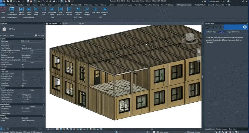
All right. So, what I’m going to start by doing is here we have a finished model. So, we’ve got these panels ready to go into Onyx. And we’ve got some floors. We’ve got some wall panels and roof panels as well, which are ready to go.
So, the first thing I want to do is I want to log into my Onyx account. So, I’ll go to Onyx. And we have Onyx, which sits inside of Revit as an additional tab. So, we want to go into our Onyx tab. And we want to link our Revit project to our Onyx web browser.
So, when I click on Onyx, it’s going to ask me to log into my account. And this is how we could create the link between Revit and our CNC machine. So, the first thing I need to do is log in. And once logged in, we can then start to link our model to our project.
If you don’t have an existing Onyx project, that’s fine. We can always create a new one. And it’s very easy to add a new project.
So, first, I’m going to switch my account. And here we can see we’ve got the Beyond the Frame project that I created earlier. Like I said, if you don’t have a project ready, you can create a new one on the fly, which is nice and handy.
So, for now, I’ll click on the Beyond the Frame project. And this is where I’m going to send my Revit geometry to. We need to specify this because we need to know exactly where we’re sending our panels and our sections.
So, with that part now done, I can upload the sections, the elements that make up the panels. So, I’m going to go to Upload Sections first. And this is our way of telling Onyx what the panels are made from.
So, you can see we have a few elements in this project, some of which may not need to be produced through Onyx. But you may need to reference their placement and their location in regards to where the panel is and how the panel looks inside of Onyx.
So, we’ve got a few things which are not defined. So, we’ve got one element that’s not defined, sorry. We’ve got another profile here, which is set to C Profile. But again, if you need to change any of the profiles, that can be done in this section if you need to override any information. Usually, it’s fine. But if you need to make any last-minute adjustments, you can do that from this box here in the middle.
To upload the sections, we simply need to check the box next to them. And we can then upload the selected elements. Like I said, we may not need to necessarily produce all of these through Onyx, but it might be handy to have these referenced in the Onyx environment.
So, I’m just going to upload, first of all, my light steel frame profiles. And if you’re working with any sheathing boards, if you’re working with different materials, for example, you can access those via these tabs. So, I want to upload the sheathing as well, just to make sure everything that is related to the panels is available inside of Onyx.
You’ll notice we have a new component section. We have an Onyx component section. Anything that is new and that Onyx does not recognize, you’ll find in the new component section. Anything that’s been uploaded will be found in the Onyx components list. So, regardless of when you’ve uploaded it, if you’ve uploaded it at least once, you’ll find it in this section.
So, the next thing I need to do is upload the whole panel. Now, we’ve told Onyx which components we’re using in the panels. Now, we need to tell Onyx what these panels actually look like.
So, when we upload the panels, you can either be specific and select a panel. And you can say, I want to upload this panel, for example. Or you can choose not to select any panels. And you can use the filters to allow Onyx, well, to filter out the panel selection.
So, we’ll go to upload panels first of all. And this is going to find all of the panels available in this project. Be it wall panels, floor panels, roofs, ceilings, trusses, any of those panel types, it will locate them.
And then we can use a range of filters. And if you’ve assigned category information, if you’ve assigned areas, we can use this information, which will speed up the selection process.
So, nearly done. Now, as you can see, we’ve got a long list of panels. If I wanted to find any specific panels by name, what I can do is use this search box and type in a value. And based on the value I type in, it’s going to find any panels which contain that value.
And you can be specific by saying, I need to find panel 10, for example. And it will find anything that contains those numbers. You can also use a range of other filters. So, we can filter by panel type, be it floor or wall panel. And you can also filter by level if you only want to upload panels on a certain level, for example.
If you’ve assigned areas to the panels, that information can be found here. And you can then filter the list by your user-defined areas. It may be handy to group panels, maybe based on a certain location or maybe based on a certain purpose, for example.
As it’s the first time we’re sending the panels into Onyx, you can see the number 1, which is our reference to say, these are version 1 of the panels. If we make any changes and upload the panels again, the versioning will reflect how many times the panel has been uploaded.
So, I’m not going to be reckless. I’m not going to upload all panels right now. But what I will do is I’ll choose to upload maybe just the panels from the ground floor.
Okay. So, I’ll pick the ground floor panels, and as I only want to upload the ground floor panels, I can then click on the checkbox, which will only show the panels on the ground floor.
If there are any components that Onyx cannot see and Onyx is not familiar with, we can check the status of those components on the right. So, if I click on one of the panels in the list, we can see that two of these elements are green, and one of the components in the panel is red. Anything that is red is not a good sign. So, that usually means that Onyx cannot recognize what this is.
So, when it comes to creating the panel, this may be missing when we’re looking at the panel. What we can do to rectify this issue is go to components upload manager, and we can upload the missing objects.
It may not be obvious, first of all, to see which object is missing. What we can do is we can go to our Onyx components, look at our sheathing boards, and potentially find any sheathing components which may be causing the issue.
I know in this case they are imperial, and we have a range of 4×8 components here. You can see we’ve got a long list of things which are already checked, which we can then delete and re-upload if we need to.
So, when we’re deleting components, it will only delete components which are not in use. Okay. So, some components were not deleted due to being linked to one or more panels. So, don’t worry about deleting something that you may be referencing. It will only delete things which are not in use.
So, now I’ve deleted a few of those components. Let me just try one more time. Okay. So, these cannot be deleted. What I’ll do is I can re-upload the components which are missing. So, let me just check one more time.
You can see here we’ve got a sheathing panel this time. And if I needed to upload it, I can go through the process again to upload those missing sheathing panels.
Okay. So, now all of the components are green, I’m simply going to upload all of the panels to Onyx.
If you need to do a visual check to see which panels exist, sorry, which panels you’re actually uploading, you can use the show button to see exactly which panels you’re referring to. And it should highlight that in the model if you need to see it.
Okay. So, what I’ll do is I’ll check all the panels, click upload, and then it will start the process of sending these panels into Onyx. Depending on the number of panels that you’re uploading, it may take a little bit of time.
And we can see in this case, it is making reference to some components which are not uploaded. So, I am going to just reference the wall panels for now. And I’ll simply say upload.
So, let me see. Sorry about that. I still had the floor panels checked, so I just need to uncheck those first.
And now once I upload the panels, we’ll get some feedback to say there are 30 panels, 43 panels, for example. It will tell you how many panels are uploading, and it will tell you which panels are successful, which ones have not been successful. If there are any issues.
So, generally, the process shouldn’t take too long. But once it’s complete, it will give us some feedback. And once the process is complete, if anything is unsuccessful when you first upload it, what I’d usually advise is if you regenerate the panel and then try again, that usually resolves the issue.
So, if you ever come across that issue, then that’s a workflow that I’ve tried, and it seems to work a lot of the time.
So, here we’ve got 43 panels, 43 wall panels, which have successfully uploaded to Onyx. So, we’ll click OK.
And once you’ve uploaded your panels to Onyx, you’ll notice a red overlay, which covers the uploaded panels. This is to give us a visual indication that something has changed.
OK. So, let me just double check. Sorry about this. I may have actually turned that off. What we have is something called a locked panel. And that locked panel will usually indicate that something has changed.
OK. Well, usually we’ll say… Oh, sorry. To the ground floor, that’s why.
OK. So, on the ground floor, you can see we’ve got this red overlay. It’s very hard to see right now because it has been hidden in this case. But you can see we’ve got a red overlay, which indicates that the panel is locked for editing.
So, I’m just going to unhide this object. OK. So, for some reason, I think it’s hidden in the view. So, it is there. It’s just quite hard to see, that’s all.
So, you can see we’ve got a locked panel. And this is to protect the panel from being edited and being made to be inconsistent with the panel that we have in Onyx.
If you need to make any last-minute changes, you can go into the Strucsoft menu, unlock the panel using Unlock Panel Group. And then you can make some adjustments to the panel again.
OK. And then you’ll see that when I try and make an adjustment or a modification, it will allow me to do that. In this case, it is a multi-layer panel. So, I would advise that you go through the multi-layer settings if you are to modify a multi-layer panel.
But in this case, you can see it allowed me to make that adjustment very quickly.
Oh, I wasn’t mute. Michael, I’m sorry to interrupt, but I’m seeing in the chat that we have a few messages saying that the demo is, they only see the 3D view and not the dialog boxes and everything.
Oh, that’s not good. OK. I think it might be down to this screen share option that I’ve used. OK. Give me two seconds. Sorry about that, guys. Thank you.
Hopefully, that rectifies it. I’m sorry about that, guys. Potentially selected the wrong option there with the screen share. Hopefully, from now on, you’ll be able to actually be on board with what I’m explaining.
OK. So, now I’ve unlocked the panel. I’ve just shown you the process on what happens when we lock and unlock a panel. Sorry, we would have missed the dialog boxes. That would have explained it a little bit better.
But I’ll just show you again very quickly what I was explaining. So, you can see here we’ve got a locked panel. If we go into the properties, you will see this dialog box related to the panel properties where you can make some changes or adjustments.
And you can see a warning here to say we can’t modify the panel unless we unlock it first. So, I’ll just close this down. Won’t make any adjustments.
And then with the panel which is unlocked, we can then go into the properties. So, as this is a multi-layer panel, we would usually go through the wall properties. But in this case, just to quickly illustrate that we can make a change, I’ll just go into the single-layer properties.
And you can see here, it’s not going to give me any warnings. Because this panel has been unlocked beforehand. Sorry, unlocked beforehand.
Okay, and we can make some adjustments there. To unlock the panel, as you may not have seen this, we can go into settings and unlock the panel from this option here. And that will allow us to remove the red overlay that would usually show.
So, what I’m going to do quickly now, guys, is run through the Onyx menu. So, we’ve got a few things here which we can use to, for example, delete a panel. So, we can unlock panels if we need to edit them. You can also delete panels if you need to remove the reference from Onyx.
So, you have the delete option there as well. You can assign areas to a panel. By assigning an area, all you need to do is select one or a few panels.
So, let me say these ones, for example. I can select these panels here. And I could say these belong to the right elevation, for example.
So, I’ll go into Onyx, assign area. And it’s based on the panel selection. So, you don’t need to select all the members, just a part of the panel.
And I could say this is part of the right elevation. Something to that effect. It is a totally user-defined criteria. So, you can define whatever you want in that area.
The feedback is telling us that there are seven panels which have been assigned to this right elevation area. And we can use this to filter the panel selection, especially when we are working in Onyx and when we’re uploading the panels.
Some of these options here allow you to quickly access some of the Onyx tools. But what I want to do today is show you the Onyx interface via the browser.
But these will allow you to access some of the tools very quickly from your Revit window without having to go to and from the Onyx web browser.
For now, I want to jump into Onyx. And usually when you first open Onyx, you will have to log in. So, I’ll just log out very quickly.
And you’ll see that the login screen has a very similar appearance to the one we saw earlier on when I logged in using the Revit window.
So, first, I’ll log into my account. If you don’t have any existing details, you can sign up. But if you do have an existing Onyx account, you can use those existing details to log in.
So, I’m just going to click sign in for now. And this will take me into my Onyx account.
So, here you can see the project that was created before. And you can see the 43 panels that we’ve just uploaded.
You can upload multiple Revit files into a project. But in this case, we only have one Revit file. But maybe you’re working with multiple sites or a cluster of buildings on a site. And you want to upload all of them into the same Onyx project. You can upload different Revit files into the same project.
So, once you’re inside of Onyx, you can see any of your existing projects. And you can also create new projects from here as well.
And what I want to do is take us to the Component Types Manager, or sorry, Component Types window. This is where we can find all of our uploaded components.
So, anything that has been previously uploaded at any time in the past, we’ll find them in the Onyx Component Types window.
So, you can see we have various different member types, which are all separated by material. So, you can see we’ve got light steel frame or light gauge steel, wood, sheathing, and hardware for clips and hold downs, and things like that.
So, if you want to be specific about the members that you’re focusing on or interacting with, on each column, you have these three lines, which will allow you to change how you interact with the column.
So, you can auto-size the column based on the size of the text. You can auto-size all columns, and you can also group the information, so you can make the table more concise if you need to do that.
You can also filter based on the column you’ve selected. You can filter certain values out. So, let’s say, for example, I wanted to find all of my 6-inch members. I can find anything that contains 600, and in the list, it will only show me results, which equate to that.
So, you can be as specific as you want, but you don’t have to be super specific if you don’t want to be.
Once you’ve found your 600 or 6-inch members, you can then uncheck anything that you don’t want to see, and you can control that quite a lot.
On the right, if you need to increase the available fields within the table, you can add additional values. You can see at the moment we have a few unchecked options, but once we add those in, you can enable and disable things that you may or may not need to see.
So, within the component types menu, we need to assign our CNC machine. So, we need to assign these members to a machine so we are aware of how to produce the CNC output, and so Onyx is aware of where the operation should be placed and which operation should be used.
So, what I’m going to do, first of all, is go into settings, and I’m going to go through the process on how we can generate some machine settings using the Howick module.
So, first of all, we need to set our units. The units can be defined at any time. These are dynamic, which means they can be changed at any time, but it’s important to set the units correctly before we start to generate our machine settings.
So, in this case, I may be working with imperial measurements, working with inches, and I may be working with fractional inches rather than decimal.
I can change the tolerance, the construction tolerance, which will affect the stacking environment, and we’ve also got a manufacturing tolerance, which will affect things like our machine settings and the outputs that we generate.
So, we’ve got our weight, so we can set the length and weight values, and again, we can set our weight to imperial, and we can define pounds as the unit of choice, and again, we’ve got the precision to control the number of decimal places.
Once you’re happy with the defined units, you can save those, and then we can start to generate our CNC machine settings.
Within the machine settings, we can define different machine types, so if you’re working with wood, you may prefer to use a saw machine, you’ve got nailing and routing, and you’ve got the multifunction bridge option here as well, if you’re working with a multifunction bridge.
So, in this case, we’re looking at a roll former, and we want to look for the Howick roll former.
So, here I’ve got a few options that I’ve defined at some time in the past, and I want to create a new setting, something that I want to use for today.
To create a new setting, on the top right, you’ll find the add setting button, and a nice thing about Onyx is a lot of the options to configure your settings are defined in the same areas, so you’ll find that it’s familiar, and the familiarity is quite easy to navigate.
So, we’ve got add setting on the top right, and once I click on add setting, you’ll see it takes us into our create new setting box, and this is related to Howick.
If you can’t see that, then, yeah, but you can see in big letters, we’ve got our Howick module. So, in gray, as a read-only value, this is related to our Howick machine.
So, this is our machine subtype, which is predefined based on the settings we just chose. We can define a setting name, which is going to allow us to identify this on a list of other settings.
This is a value to help us to identify which members may need this setting, and to allocate them, well, more correctly or specifically.
So, I’m going to say this is HWK, and it’s going to be for six-inch members, for example. You may want to create a more accurate naming convention, but it’s totally up to you, and it’s based on how you want to assign these to your members.
You may have a machine that is capable of rolling multiple members. You may have a machine or separate machines that carry out different members or can create different members, in which case you may want to create a variation of machine settings and assign those accordingly.
But I’ll go through the process anyway, and it should become clearer.
So, again, our units are set as read-only values. We can’t redefine these, and once you create your settings, they are locked to the measurements that you’ve defined and the units that you’ve defined.
So, it’s important to set these correctly first.
After that, we’ve got some machine options related to the operations that we want to carry out on our machine, so the size of the operation.
So, based on your machine and its capabilities, you will need to define a value based on the tooling on your machine and the settings for your specific machine type.
So, in this case, we can set the web punch width, a lip notch width, or we can define a value for the width of our operation. And in some cases, you may need to punch twice.
So, define the width based on the tool, and it will place as many operations as it needs to, to recreate the punch that you need.
So, you’ve got Swage Tool Width, Dimple, Minimum Edge Distance. So, we’ve got a few different settings here.
We do try and cater for a wide range of Howick machines, as well as other machines as well. So, you may find some settings in your, or some parameters within the settings, which may not be applicable.
If that’s the case, just set the values to zero, and in some cases, you can uncheck the options to say, this is not applicable, in my case, or for these settings.
So, in the machine options, these are general settings related to the operations, and we can add separation distances for our flange slots, include the tool tolerance based on the width of the tooling or blades that we may be using if you’re cutting things.
And then we’ve got website to center diameter, a load of things related to operations and the sizes that we want to use.
In the general settings, this is where we can add additional functionality based on our machine and its capabilities.
So, you can, for example, use version 2.0. This may not be a setting that’s available on all Howick machines, but it may be applicable to specific ones.
If you work with slotted dimples, you can enable that setting as well, and you can also disable it. So, in some cases, you can uncheck the options if it’s not applicable.
Again, default profile, this may be an option on your machine. Just check your machine settings in order to make sure that this is compatible and the settings are consistent.
If you want to include the panel ID when you’re generating your machine settings or your CNC output, then you can include the panel ID as well, and it’s going to filter out the settings based on the panel, specific panel ID.
When you set the members to vertically, sorry, vertical joists to be structurally critical, so verticals or floor joists to be structurally critical, that means those members won’t receive any operations that may compromise the strength or affect the strength of the member.
So, any web cuts or web notches, those won’t be placed on any of those structurally critical members.
There are other settings here as well. I won’t go for every single one, guys, but we do have a range of settings.
For example, we can use a profile description in the file output. We’ve got to use stud spacing tolerance to adjust the stud spacing if we need to account for stud adjustments, maybe in Heist, for example, and you can use the stud spacing tolerance for that.
You can add a sequence number to the output file name. So, if you’ve assigned sequencing, you can use that in the file output.
And we’ve got things like folded ends, again, which may be specific to your workflow or may not be specific to your workflow.
If you want to replace dimples, you’ve got the option to do that. You can add extra flange slots at the ends of the top track.
So, some of these are very specific and they may not be part of your workflow. But like I said before, these can be enabled and disabled as needed.
If you want to have a continuous bottom track on your door opening, you can then apply courtesy cuts to make it easier to remove that section within the door. And there’s some options here which allow you to do that.
So, maybe you have a specific convention for creating your file outputs. So, maybe the top member needs to be first in the list, then the bottom member next, and then left to right members in that order.
You can define how the output is created and how the members are ordered in the list. So, from top to bottom, it’s going to follow this order, top member, bottom member, left, and then all the way to the right-hand side.
If you prefer to have null order, you can also just generate the file with null particular order, maybe based on how it’s defined in the table in the panel manager.
So, once you’ve defined your settings, given them a name, changed all the values, you can then hit the create button.
Okay, I think I know what went wrong there. So, just be careful when you’re creating your settings, guys, when you’re using things like inch symbols and those kind of things, because those will affect how the settings are created.
So, you’ll see here, if I add a six-inch symbol, it is going to tell me that something went wrong.
Okay. So, in the name, let’s say, for example, HWK 600. Okay. That’ll be my six-inch members in this case. And then, yeah, we can redefine the settings if we need to.
All right. So, once we’ve defined the new settings, you’ll find we can create multiple settings for different purposes.
Maybe you’re working with four-inch members, six-inch members, three-and-five-eighths. You may need different settings for different purposes.
So, in that case, you can, maybe you need to create different size operations on the two separate members. Maybe one has lip cuts, which are slightly smaller. Maybe one has web notches, which are slightly wider.
In that case, that will be a cause for creating a new setting, and you can assign those accordingly to the different member types.
So, I’m just going to quickly add another variation, just to illustrate what I’m talking about. So, I’ll say HWK, and I’ll say 400, for example. Okay.
I’m not going to change any settings, but I will say create for now, just to show you that we can assign as many settings specifically to the members that we need.
So, once you’ve created your settings, you don’t need to click Save or anything like that. We can then just click out of this menu and go to Component Types.
So, within Component Types, this is, again, is a list of all of the profiles available, and I want to assign my machine settings accordingly.
So, I’ve got some 600 members, and I’ve got some 400 members. What I want to do is make sure I’m assigning the right size members to the right things.
So, I’m going to go into my type name, and this is where I can select things based on the size. So, this is going to be the easiest way to select the profile by size.
Another value we could use is Depth as well. So, I’m going to go into the properties related to this column, and I want to filter by typing in 600.
With all of the 600 members selected, I can then select all of these elements in the list, and maybe I use the same machine for all of these member sizes.
In your workflow, I imagine you won’t need to have this many members, but in this case, we can say Assign CNC Machine. Choose the machine type, and then we can choose the settings that we want to apply to these selected members.
As I said before, there is quite a lot of control that you have based on the different settings. You can assign different settings to different members specifically.
Okay. So, say, for example, Assign this with the HWK600, and on the right where it says CNC Machine, you can see what has been assigned to these members.
All right. So, I’ll do the same with the 400 members. You’ll notice I didn’t make any real changes to the settings, but this would have to be specific to your workflow.
So, in this case, I am working with 4-inch and 6-inch members in the model, and, yeah, we’ll have a look at what it needs to do.
So, 400, Select, and we’ll assign the HWK400 settings. So, again, we’ll go to Machine, Subtype, or, sorry, Machine Type, HWK, and we’ll choose HWK400. And we can assign those settings accordingly.
In the event that there are members that you’ve uploaded to Onyx, but they don’t necessarily need to be produced as part of the panel. You’re just referencing their location.
You’ve got two options. Option one, any components that have been uploaded to Onyx, by default, are set to Unassigned. So, that means they’re not linked to a machine.
If you want to leave them unlinked from a machine, you will see a message when you do create your output to say that certain members have not been assigned to a machine.
The other option is to set them to Do Not Roll. So, if you select a member and you say, I don’t need to generate the output related to this member, but I do need to reference its position.
I don’t need to create any operations, any cuts, any dimples, or anything like that. I just want to show where it is in the panel.
So, in that case, you may have things like U-Tracks, which you want to use in the panel. So, we’ve got a track here. And we can set members like this to Do Not Roll.
Maybe you purchase certain families and you prefer to just show their location in the panel, but you don’t need to create an output related to it.
So, you can select anything that you want. So, for example, the Semco family. And I can go to Do Not Roll. And we can assign this value to any selected member.
Okay. We’ve got there in the end. Okay. So, you can see it’s set to Do Not Roll.
By default, the dimple position on the panel members is set to the center of a member, but we also have options to also add a dimple line shift. And we have a parameter here, which is specifically for that purpose, to offset the dimple away from the center.
So, you’ll see that we’ve got dimple line shift. And when we have a dimple line shift in the panel, we can select specific members, we can go to Edit Parameter, and we can define a value to shift the dimple away from the center point, for example.
So, maybe we need the dimple to move to the left by an inch, in which case we can do that kind of thing as well. Okay. So, you can add a dimple line shift that way. No pressure, but the option is there.
All right. If you need to share this table or any of the information within the table with a third party, you can export this to CSV, and you can share it with someone who may not have access to Onyx.
This is really handy because they’ll be able to view the file in Excel or any other file, Notepad, for example, that can handle CSV files or files which have a TXT kind of extension.
All right. So, what I’m going to do now is go into our project. And now we’ve assigned the members or the components to a machine, we can then generate an output related to those members.
So, I’m going to go inside of the Beyond the Frame project. Within the project, by default, it takes us into the Panel Manager.
The Panel Manager is a centralized location where we can find all of our panels, be it wall panels, floor panels, ceilings, trusses. They’ll all be housed in the appropriate location.
So, in this case, we are referring to walls as we only uploaded walls in this case.
We have some settings along the top, which will allow us to delete panels if we don’t need to reference them in Onyx anymore. And this is similar to the delete function that I showed you earlier in our Revit project.
You can also generate reports related to the panel where you can extract things like the panel name, panel length, total number of members. You can also grab information related to material, coil width, these kind of things, all found within the report that we can generate.
Export to CSV, again, this will allow us to export the panels based on the current structure of the table. Our report will be exported in this format.
So, you can change the order of the information. You can move things around if you need to. And you can remove any values that you may not need to reference, for example.
If you want to download your panel straight away, you have the option to do that. But, you can reorder the panels in the list by using ascending order, descending order, and you can set it to show no order.
But, if we say ascending order, you can see here we’ve got panel 176. And, if I wanted to download panel 176, maybe it’s ready to be downloaded straight away. We can do that.
And, you can see we’ve got a few things here which have not been assigned to a machine. I did think I had all those members assigned. But, you can see we’ve got a light gauge stud family here which has not been assigned.
Okay. Okay. So, I can fix that really quickly. Okay. So, I’m going to go through component types. And, I just want to make sure that the 150 members are also considered as well.
Okay. So, that’s C1. I’ll just say C. Just so I can capture all of them at once. Okay.
So, I’m going to say all of the C members. And, I’m going to make sure that these are assigned to the Howick machine as well.
So, in this case, I will use one of my generic Howick settings. Which will cater for most of these members.
Okay. So, again, we can generate some settings related to these. The C150s are metric families. So, I may have actually had a metric reference in the families in the project. Which I may have forgot about.
All right. I’m getting old. So, my memory. Yeah. Okay.
So, when we go back into the project. What we’ll be able to do is go into the panel manager. And, again, I’m going to attempt to download a panel.
I’m going to go to panel name. Panel 176. And, again, I’m going to attempt to download CNC.
What we should find is, first of all, we’ve got the project name. Which is a good indication that this actually happened this time.
And, we can see some of the components in the panel have not been assigned to a machine. This is the same warning that you’ll see when you leave your member set to unassigned.
So, if it’s unassigned, it’s not assigned to a machine. It’s very easy to fix the issue. You just need to assign the member to a machine. So, Onyx is aware of how to create it.
For the members that did work, you can see we have generated an output for panel 176. And, this is the member type that we’re referring to, C150.
So, based on the members that were successful, you can see we’ve got our component list, we’ve got the orientation of the members, and we’ve got the placement of the operations all shown on the right.
So, you can see this is what our Howick file looks like, and we can see the extent of all of the operations in the panel based on these members.
Okay, so, if you prefer to check the panels before you download them, which I would suggest, we have something called the CNC Editor.
Within the CNC Editor, this is a great place to do a visual check on the panels and also add some last-minute changes.
Before I jump into the CNC Editor, I just want to draw your attention to some of the things you may see when you download a panel.
So, I did just download a panel, but for now, you’ll see this status. So, we’ve got the Profile Status, which is set to New. This tells us that this panel has not been downloaded. It hasn’t really had much interaction at the moment.
So, with panel 177 selected, if I click Download CNC, what we should see is a new status for the selected panel.
Let me just check this out, guys. Okay, I’m pretty sure I did assign it from. Okay, I totally forgot about that.
Okay, so, we’ve got some foam in the panels, and I forgot to remove it. That’s going to cause a little bit of a headache, but I’ll try my best to get around it.
Okay, so, we can download the panel, and when you download all of the components of the panel, so, if I go to panel 177, for example, at the top, this is showing us the overall panel. All of the members of the panel, the whole panel.
At the bottom section, this is showing us a reference to all of the members in the panel. So, these are all of our verticals, horizontal members, our tracks, cripples, headers, all these kind of things.
So, based on the members, you may prefer to download only a few of the members at once. So, maybe I want to download just the top and bottom track, and maybe the end studs as well.
So, if I choose to download only these members, you’ll see that within our outputs, it’s really strange that it’s still showing me that, it shows us the members which were downloaded and related to the ones that were selected.
Okay, so, we can select just a few members at one time as well.
Okay. So, usually what happens is when you download a panel, the status will change to update the information related to that.
I can tell you why it’s not doing that right now. It’s related to the foam that was uploaded along with the panel.
So, I’ll just show you that quickly, just so you’re aware of how to troubleshoot this issue.
You can see we’ve got sheathing boards, but we’ve also got foam, which has been modeled within the panels as well.
So, if you remove the foam, upload a panel, it should get around the issue.
So, what I can do quickly, guys, is I’ll show you how to do that.
Okay, so, I’ll go to Strucsoft, Properties, Miscellaneous. You’ll see that we have foam in our settings and very easy to remove.
Sorry, let me just go back. This is a multi-layer panel, so let me just change it in multi-layer.
Okay, yep. So, Strucsoft, Operations, Wall Properties. Indeed.
Okay, so, I’ll unlock the panel first. Once we go into Wall Properties, we can see the wall buildup or the composition of the panel.
And I want to go into the Structural Layer, edit the settings, and this is where I can remove the existing foam, which is in the panel.
Okay. So, right now, this is assigned. I can simply set this to None, click OK, and that will remove the foam from the panel.
So, now it’s removed. We can then go through Onyx, Panel 176. Let’s just quickly upload this one again, guys.
Sorry about this. But as this panel has been uploaded once before, we should be able to see that this is version 2.
And this is a good time to explain when we upload a panel for the second time. If it’s unlocked, it will have a version 1 reference within Onyx.
So, when you upload a panel again, it will become version 2 after that. So, you will be able to see the version in. The existing version 1 will be removed.
So, you won’t have any reference to that inside of Onyx, which is a good thing because you don’t want to have two references and incorrectly create the wrong panel.
So, with Panel 176 selected, we can check for any components which have not been uploaded. And, again, just double-check that everything goes into Onyx correctly.
OK. Do a last-minute check and then upload.
OK. So, now that panel has been sent into Onyx, we will be able to see the versioning. You can see that as an additional field as well if you are interested in seeing the version.
And you can see here with version, if I just refresh the browser quickly, we’ll see that Panel 176 should show as version 2.
You can see there, Panel 176, sorry, version 2.
So, now I’m going to go into the CNC editor.
Oh, sorry. Before I do that, before I just download the panel quickly, it’s always handy to see what can go wrong in the webinar because it’s always also nice to know how to fix it.
So, you can see Panel 176, and now the status has changed to downloaded. So, the thing that was affecting it was the foam insulation in that case.
So, if you wanted to check a panel before you download it, if you go to the CNC editor, this is where you can make adjustments to the panel.
As I said, these are going to be last-minute adjustments that you need to make in regards to additional operations, maybe moving existing operations.
But the changes that you can make are going to be minor changes. Not big changes, for example, you can’t add additional members, you can’t make any physical adjustments to the look or appearance of the panel.
It’s all going to be related to the operations that you can place within Onyx.
So, on the left, we’ve got a filter, and we can use this to filter out specific panels, maybe based on an existing work order.
If you’ve created a batch of panels which need to have a deadline assigned to them, they need to be produced by a certain date or time.
We’ve got the file. If you’re working with multiple Revit files, you can filter by the Revit files.
Area, if you’ve created an area or assigned a panel to an area, you can also say, show me the panels which are assigned to the right elevation, for example.
You’ve got level, which is ground floor. If we uploaded the other levels as well, those would be available in the list.
And we can also filter by panel type, wall, floor, ceiling, truss.
For any panels that have been assigned a category, you can also use the category information to filter down the list and make it easier to select only the elements that are relevant at the same time or at the right time.
So, once I load the panels which are in the right elevation, you’ll see I only have panel 176, which meets the criteria.
So, based on the filter criteria that was selected, only one panel meets that criteria.
So, go to panels, panel 176, and this is how our panel looks.
So, we can see our operations. These are placed automatically. So, many of the standard operations, for example, dimples, lip cuts, web notches, these kind of things are placed automatically.
One, based on the settings defined in our machine settings or our CNC machine settings. And two, based on how our members are interacting within our model.
So, if I just draw your attention to panel 176, I’m going to pick on this one now because it’s working. And let’s have a look at the panel in a coarse level of detail.
So, in a coarse level of detail, our panel studs now look like lines. Okay. So, let me just find the sheathing board. I want to get rid of that. And this.
Okay. So, here are our members in the panel. This is our bottom track. These are my verticals.
And you can see, based on the position of these elements and how the lines are overlapping. Sorry about this. It’s taking a while to show the members.
But based on how the members are interacting, you can see that the dimples are placed based on how the lines are crossing.
So, as this line is crossing over this one, it knows there’s a connection between those members. If there isn’t a connection between the members, so if this line, for example, is stopping short, you may not see the operation show up in Onyx.
So, just make sure all of the lines are crossing over as they should be. And that will help, especially when trying to show things like this in Onyx.
All right. So, what we have here is our panel. And we can see a lot of the operations are placed by default, as I mentioned before.
If we needed to change the priority of the members. So, right now, this vertical member here has priority over the top track.
If I go to Invert Connections, you’ll see that this red arrow is parallel to this vertical member. Which means we’re going to have to notch this member in order for this one to be prioritized and pass through.
If you need to override any of the settings, you can change the priority of the members by simply clicking on the red arrow. And that is going to switch the priority to this member.
And now this member needs to be notched in order for this one to take precedence and to pass through.
Okay. So, you can make adjustments like that.
Another thing that might be handy to do is change the visibility settings. So, right now, we’re seeing the operations in a shaded view.
When it’s set to shaded, the operation show with colors. You can also set the view to shaded and cut, which will give you an indication as to how these members will look once the operations have been carried out.
So, once these cuts have been applied, this is how the member is going to look. So, you can see where our lip cuts are. And you can see a better indication of how the members will look once they’ve been produced.
For any last minute operations that you need to add to the panel, we can add those by selecting a specific member. And going to LGS operations.
Here is a list of all of these different types of operations that you may want to add to the panel.
So, for example, I may need to add a service hole. So, I can just click to place a service hole and define the position of the service hole.
So, maybe 30 inches, for example. You can also extend horizontal members. So, we can add operations. We can move them around.
We’ve also got grips to move them around as well. But we can also extend things like horizontal members.
So, let’s say, for example, I need this member here to extend to that vertical member. If I go to general, we’ve got a setting called trim extend horizontals, where I can make some…
You could say these are physical adjustments to the panel, but we’re not creating anything new. This is using what is already existing.
And I can extend the reference to one of the neighboring members. So, we can do things like that, for example.
I can’t create a new member out of nowhere. It has to be an existing member for that to work.
If there are any members in the panel that you want to exclude from the CNC, you can simply exclude them. And then the information won’t be included in the CNC when you produce it.
Within the CNC editor, you can get a preview as to what the code will look like in the CNC file. And you can go to the code viewer in order to see that.
So, here’s our panel. And when I select a member, you can see it will highlight the data in the CNC or the code in order to show us the operations, the location of the operations, those kind of things.
You can see it does highlight the information based on what we’re selecting in the panel.
Okay, so that’s just some of the things we can do within the CNC editor. You can also download the panel from this location as well, once you’ve checked the panel.
Okay, so those are a few things we can do. So, we have the download button there.
So, once you’ve downloaded your panels, what you can do is you can sequence the panels in a sequencing window. And you can also choose how to distribute the panels to site using these stacking features.
Sequencing is a very quick operation where you can select the panels in a specific order and assign a sequence number to the panels based on how you’ve selected them.
So, if I go into sequencing, first of all, on the left, we have a filter. And on the right, we have our viewing window.
Again, we can set the criteria by defining things to filter out. And maybe in this case, I’m going to load all of these panels on the ground floor.
So, here are the panels. And you can see these are the panels on the ground floor.
So, in many areas, there is foam. And that’s why the panels look quite larger than they should. But what the panels should look like is they should look like this.
Okay, so you should be able to see each panel and how it’s positioned based on the members. You can see the foam reference there, which is slightly oversized.
So, if I wanted to assign a sequence to these panels, how can I do it?
I’ve got two options. Option one, we sequence by selection. So, if I click on the sequence tool, I can then select the panels in a specific order.
And once I do, you’ll see each panel, when I select it, will be given a number in brackets.
So, in this case, panel 221 is number one. And as I continue to select the panels, they’ll be given a number according to the order in which they were selected.
Okay. So, that is option one. And once you’re finished, you can hit save, and the sequence will be saved to the panels.
You’ll be able to see an indication in brackets to say which panels have been sequenced.
Option two is if you prefer to sequence the panels based on the number assigned to the panels.
So, maybe you’ve created your Revit model, and you’ve assigned the panel numbers in the Revit model in a sequence.
If you prefer to use the numbering based on the sequence that you’ve assigned to the panel names, you can go to Convert Panel ID, choose the sequence that you’d like to use, and you can convert the panel ID.
I’m going to quickly create a new sequence, because otherwise it’s going to override my existing one, and I’ll show you how to do that quickly.
So, we go to Project Settings, and I’ll just create a new sequence called Ground Floor EXT.
Okay. So, these are my exterior walls on the ground floor, and when I go back to Sequencing, I’ll be able to assign those panels to the new sequence.
It won’t be much longer, guys. I know it’s a long one, but we’re almost through the sequencing part.
All right. So, again, within this menu, we’ve got coarse or fine level of detail. I want to set it to fine so I can see each independent panel, and I want to use the filter to select only the exterior walls on the ground floor.
So, I’ll say Load Panels, which will only produce the exterior walls.
So, maybe if you prefer to work with certain areas of the model at one time, you can use the filter to control a lot of that.
So, I’ll go to Sequencing, and I want to set the sequence to Ground Floor EXT.
I’ve also got access to the Stacking Sequence. So, if I select the Stacking Sequence, you can see there are numbers based on the sequence that is applied to those existing panels.
But if I go to my New Sequence, you’ll see that the sequence is totally empty.
So, I want to convert the panels based on their ID, and this will assign a number to the panels based on, well, the numbers that are assigned to the panels.
In the General tab, I can play an animation to show me what the order of the panels is.
You can see it’s quite sporadic. It’s all over the place a little bit.
But you can assign a sequence by selection as well, or you can number them in a more consistent way in your Revit model.
So, that’s the Sequencing tool.
Once you’ve sequenced the panels, the sequence can be useful within the Stacking Environment. It can be useful in many different places.
In the Stacking Environment, if you want to stack your panels and define how they’re going to be grouped for distribution, the only things you’ll need to pre-define, guys, is the Stacking Settings.
So, you’ll have to create some templates related to bundles, pallets, trucks.
So, bundles are the smallest of the container types, but this is going to group your wall panels, for example, and then you can place them on a truck directly after you’ve placed them in a bundle.
If you also work with pallets when lifting panels, you can also use the pallets option as well, which is similar to a bundle, just has a pallet at the base as well.
And then for our trucks, this is how we can distribute the panels to site. We can define the size of a vehicle in order to distribute the panels to site.
Okay, so what I’m going to do first, so I have pre-defined some of these settings just to save some time, because I knew this would potentially overrun.
But I’m going to go back to my project, and I’m going to go into my projects beyond the frame.
From there, I’m going to go to Project Viewer, and I want to enter a new stacking session.
I’m going to keep it very short, guys. I won’t go overboard with this one, because I know I’m conscious of time.
So, if I want to create a new stacking session, on the top right, this is how we can create a new session.
Any existing sessions will be found in a list view here, with information related to the ID, the name of the project, the time it was last modified, and all of the panels, which are placed in bundles, pallets, and trucks.
So, it’ll be giving you a nice breakdown of those panels.
So, I’ll click on New Session, and again, we’ve got the filter option to define which panels we want to interact with.
And again, maybe I’ll keep it short, and stick to the exterior wall panels, in this case.
So, I’m going to load in the exterior walls, and I want to place all of my exterior walls in a container.
As I said before, I’ve predefined some bundles and pallets. I’m going to stick to the bundles for now.
And we can place things in the containers by going into the Stacking tab, and we can say, add bundle, add a pallet, or add a truck.
So, we can choose to place panels directly on a truck, or we can place them in a container first.
So, this is a view related to our panels. We can also create views related to the container that we want to add the panels to.
So, if I click add bundle, on the right, you’ll see that we have a bundle container related to the panels that I’m going to place in there.
You can generate different templates with different size containers. So, here I’ve got a large option.
And if I set that, you can see we can resize it based on the constraints that we’re working to with our panels.
When we place the panels in the containers, they are placed, stacked one above the other.
Okay, so, it won’t assemble them as a configured unit. It will be panel by panel, and we can then set them on top of each other like this.
You can also select multiple panels, and you can add those either by dragging and dropping, or you can use the plus sign in order to add those as well.
If you’ve added too many panels to any one container, you can remove them. So, you can see here, remove from container, or you can use the delete key on the keyboard.
If you need to resize the container, you can click on the shrink button or stretch, and this will resize it around the panels inside of it.
So, you can see it’s giving us a little bit more flexibility.
Once you’re happy with the settings, you can then hit the tick, and this will confirm the container.
You may also want to stack things a little bit quicker than this.
Okay, so, based on the number of panels, doing them one by one, deleting things, moving them around, may be a bit time consuming.
If you’re short on time, we have some automation that we can use for stacking panels.
You can stack by path, which means you define a line, and based on the line passing over certain panels, they’ll be added to the stack or the bundle in that order.
We can also stack by sequence, which is going to use the sequence number that was generated using the sequencing tools.
So, you may prefer to use this method. It may prove to be quicker.
So, I’m going to choose my large bundle, and I want to use the ground floor EXT sequencing.
I click SET, and the sequence type GF does not include all of the scene panels. That’s fine, because I didn’t load in the interior walls. I didn’t load in any floor panels.
You can see it’s not containing all of the panels in this project, some of the interior walls, for example.
Any panels which may need addressing, we can double-click to re-access those at any time, and we can resize this as and when we need to.
You can also move things in the container as well. So, let’s say, for example, I need to move this panel to the side.
We’ve got some move tools, which we can use to move things up and down, left and right, and we can relocate things as necessary.
To remove any empty space beneath a panel, you can collapse it, and then we can simply shrink the container again, like we did previously.
Okay. I’m just going to quickly make that adjustment here as well.
In real life, I’m pretty sure we can’t resize the containers when we’ve got a constraint, but just configure the size of the container to match your constraints. You can’t go wrong.
All right. So, now we’ve got all of our panels placed in a container.
I want to place these on a truck. I won’t go through the pallet option, because it’s very similar to bundles, but in this case, I will add a truck, and we want to place these bundles directly on this truck.
So, I can select the bundle, and again, I can drag and drop these where I believe they’re best placed.
We have two views available, which means I can see the truck from the top, and I can see the truck from the side.
This will make it easier for me to maneuver these elements in two different view orientations.
So, maybe in this view, I need to move the bundles over, and in the side view, I need to move things down.
So, again, I can use the collapse tool to remove any empty space, which is going to allow me to work with this a little bit more easily.
So, again, drag and drop, and based on the size of the elements, we may need to move things around a bit.
Okay. Sorry about this, guys. Aye, aye, aye.
Okay. Let me just collapse that quickly, and then I’ll finalize with these last couple of bundles.
There we go. All right. So, let me move this one to the side, and just collapse.
And again, this one may just about fit. Okay. It’s a very tight one. I’ll let you guys decide.
But then we’re going to hit the green tick, and this is our truck.
Okay. So, based on the size of the truck and the constraints we’re working with, based on our truck size, this is how we could stack the panels within the truck.
If you need to rotate the panels or move them around, you can see here within this window, I can, well, I guess I’m moving the truck in this case, but if you need to move anything, for example, if you need to rotate the panels, we can edit a selected bundle at any time.
So, if I go to this one, I can click edit, and if I want to rotate the whole bundle, we’ve got things like rotate.
Sorry about this. which will allow me to rotate the bundle.
Why is it doing the whole thing? Okay. Sorry about this. I might have to pull it off the truck first.
So, we’ve grabbed this guy, for example, and if we need to rotate a whole container, you can then use these tools here in order to interact with the containers, the whole container, not just part of it.
Tell you what. There we go. Got there in the end.
Okay. So, you can interact with the whole container. Maybe you need to stack the panels on their side, or you need to stack them flat. You can change orientation.
All right. Perfect.
Okay. So, finally, once you’ve placed them all in a truck, you can publish the session.
So, we can go to general, publish our stacking session, and that means it’s going to be saved as a finalized session.
So, I’m going to call this one beyond the frame. Click OK.
The session will be published, and after that, we can start to generate a stacking report.
So, we can go into the stacking center, and we can generate a report from the bundles, pallets, and trucks that we’ve placed in the project.
So, if I click on the truck, I can see what is in the truck. So, which panels are in the truck, which bundles, and I can see all of the information in one place.
So, this truck contains all of these panels. It may contain bundles. It may not. It may contain pallets. It may not.
Okay, guys. Just a moment. It may load. It may not. Hopefully, it does. If not, then I guess that will mark the end of the webinar.
Okay. I don’t think it’s going to load, so I’m going to call it there for now. Just because it may take some time.
Okay. All right.
So, in the stacking center, yes, this is where we can see all of our bundles. You can see a load of panels inside of our truck.
You can see the bundles in the truck as well, and it gives us a clear breakdown of what is within the containers that we’ve created.
You can also generate a report, and this will give us a breakdown and a sheet related to all of the elements in the selected container.
So, in this case, the truck. I can say, generate a report for selected, and then it’s going to create a report for us.
Okay. So, here’s the report, and within the report, you can see our truck, the contents of the truck in regards to the bundles.
So, we’ve got bundles one, two, six. We’ve got a breakdown of the information.
So, for example, this is our truck. It’s a bit slow to catch up.
We’ve got the individual bundle totals. So, I’ve got the wall area based on all of the panels.
You’ve got the weight of all of the panels as well. All of this information can be included in the stacking templates.
We’ve got the panel numbers. So, we can see each panel, which panels exist in the bundles, and we can see a front and side elevation, and it gives us a clear breakdown of all of the panels, weight, wall area, the levels, all this kind of stuff that you may need to track when you’re distributing the panels to site.
Okay. In that case, guys, that’s the end of the webinar.
Hopefully, you’ve got loads of questions. If not, that’s great as well. That’s the end of the webinar.
Hi, Clemens. Hey, Michael. Can you hear me?
Yeah, I can hear you now. Yeah. Yes. I had trouble all getting into the stream.
So, before we close the webinar, we do have a question from Hammond. So, he’s asking, does Onyx integrate with FrameCAD systems and match machines?
So, at the moment, we are working on, well, we do have a FrameCAD functionality where we can produce a FIM file, which will work with FrameCAD, but we can’t directly export to FrameCAD at the moment, but we do have a workflow that allows you to work with FrameCAD.
Okay. Amazing. Thank you.
I think we can wrap this webinar. So, thank you so much, Michael, for this insightful presentation, and thank you all for joining us today.
We hope you’re leaving with ideas to elevate fabrication planning and drive more efficient off-site assembly workflows with Onyx.
So, on behalf of Graitec, we appreciate your time and participation, and we look forward to seeing you on the next session.
Thank you, Michael. Thank you.
Bye.
Some of our international clients that use our software