How to Frame Wood Trusses Efficiently with Strucsoft
Date
Duration
Speaker

Michael James
Technical Consultant
Watch the recording
What’s the webinar about?
Join us for an in-depth webinar on streamlining the design of wood trusses with Strucsoft’s plugins. This webinar is a must-watch for for structural engineers, designers and detailers who want to simplify truss design and engineering in Revit. Our presenter will walk you through a step-by-step process for your Revit models all the way to creating trusses from envelopes. By the end of this session, you will have the tools to bring greater precision and efficiency to your Revit projects. Don’t miss this insightful presentation.
What you’ll learn
- How to properly prepare a Revit model for wood truss framing
- The process of loading appropriate truss families
- Step-by-step methods to generate truss envelopes
- How to create physical trusses from envelopes
Read the full video transcript
So welcome to the webinar everyone and today we’re gonna go through a topic called how to frame wood trusses effectively using Strucsoft.
So we recently went through a name change from MWF. Many of you will be familiar with the name MWF but we’re now called Strucsoftso if you hear me refer to Strucsoft it is still MWF.
So during this webinar I hope to cover the following topics. So I’m going to go through how to prepare your model for framing wood trusses, loading appropriate truss families so you can frame using various types of families, creating envelopes using the truss tools and then ultimately creating our trusses from the truss envelopes that we generate.
So the first thing I’m going to go through is how we can prepare our model for modeling with the wood trusses. So first we want to make sure our wall buildup is set and ready for framing trusses.
So I’m going to select one of these roofs. The types are both the same but if we take a look at the composition of the roof you’ll see that in the structure we have a single structural layer. Unlike walls, roofs aren’t affected by the structural layer rule so you can have multiple elements within the structural layer here because when we frame our trusses, when we frame with roofs, Strucsoft is taking into consideration the whole roof composition, the whole roof buildup.
So here we have multiple layers and when we define our trusses, when we define the placement of our trusses, what we need to consider is where those trusses are going to be located in the overall roof buildup. So for example, on the exterior side of the roof we have a finished layer which is one inch thick and we have a substrate layer which is also one inch thick. Our framing members are then placed after our membrane layer which has zero thickness.
So what I need to consider right now is the two inch layer that we need to leave free for the substrate, for our wood battens and our roof tiles in this case. So I want to place these structural framing members two inches from the top. Okay so we’ll bear that in mind when I start framing and it will make sense.
All right so that’s one of the main things we want to consider regarding the roof.
Next we want to make sure that we have an understanding of the kind of trusses we want to create because we can create trusses in loads of different ways and there’s various tools to create trusses in different ways. So it’s a good idea to have an idea of how you want to generate your trusses when you’re aiming to make those.
Okay another thing we want to consider as well. So this is not really roof related this is more of a wall related element. With our walls we can set them as a structural material and by setting it as a structural material it can then be treated as a supporting element for our trusses. So when we select the wall the truss will then recognize it as the supporting element.
So I’m going to select the wall and we’ll just one of these walls on the first floor, go to edit type and then in the structure you’ll see that we have our wall composition, multiple layers as you can see. The main thing that I want to draw your attention to is our structural layer in between the core boundaries and that this layer is set as a structural material. So you can see the checkbox here is highlighted and this will tell MWF or tell Strucsoft that this can be a supporting element for our trusses.
All right. So I’ll click OK on that one. Hit OK. And that’s pretty much the main things I would advise you to set up when creating your framing or when you plan to make your framing for trusses. There may be other things as well but those are the first things that come to mind.
Okay so second of all what we want to do is load in appropriate truss families. So we want to load in different member sizes so we can generate trusses of different sizes, use different members within the trusses. Funnily enough we don’t have to load in truss specific families. We can load in wall framing families when we’re working with wood and those will also work as well.
So what I’m going to do is go to the Insert tab, Load Family and then from there you can see it’s taken us to our location where we can find all of our Strucsoft related family components. So I’m going to go to the 2024 folder. I’m working in 2024 today. And I’m going to go to the Trusses menu.
So you’ll see here we have various categories. We’ve got floors, walls, trusses as we can frame in those different categories. So if I go to Trusses you’ll see we have framing components. We have the choice of metric or imperial. For today I’ll just use imperial but metric is also available. And we can use Manufacturer Families or Standard. I’ll go for Standard.
And here we have the option to choose wood families, LGS families and the placeholder as well. We’re looking at wood today so I’m going to select the Dimension Lumber and hit Open. And we can load in families from this truss related folder.
As mentioned before we don’t need to load them specifically from the Truss folder. We can also work with any lumber that’s already preloaded. So I’m going to load in just a few options here 2×3, 2×4 and maybe a 2×8. Usually by default we have a 2×6 in the file so I’m not going to load that one. But if you needed to you could also load any other sizes you need.
So once those are loaded we can now use those to frame our trusses.
All right so what I’m going to do now is go into the process of how we can generate truss envelopes for our trusses. So what I’m going to do is go to MWF. In the MWF menu we have the truss module so we can activate the truss module from our MWF or Strucsoft menu on the left and we can focus specifically on the truss related tools.
From here we have different ways of generating profiles or envelopes that we can use to generate our trusses. I’m going to draw my focus to the main element, the main roof in this model for now and I will hope to frame all of these elements that you can see all of these roof related elements.
So I’m just going to switch to my main roof view where you can see we have our roof, we have walls, some other elements. Main focus is our roof.
So to start generating envelopes for the roof we need to first select the roof as the host element, go to MWF and we have a couple of options here. So I could generate an envelope for the main roof using the common option which will generate a truss envelope with a supporting king member in the middle. If you prefer not to have that king post in the middle we can also just hit the create option and this will do the same thing generate an envelope just without that middle support.
So with this create option selected on the truss model panel I’m going to select my supports. So the first thing it’s going to ask me to do is select the supporting elements for the truss. So I’m going to click on supports and I’m going to choose the wall which is facing us here on the right hand side and I’m going to select the wall on the opposite side on the left hand side here as well. So these are the two supports I’m selecting.
Once I’ve selected them I can hit finish and once you’ve selected your supports you will see a window like this where you can specify how you want to align your heels in relation to your wall or if you’re selecting a beam if you’ve got any wall framing in place you can also select a beam option as well.
So as I’ve selected a wall you can see we’ve got two alignment options structural layer which is taking into consideration the core layer within the wall. We can align to parts of the core layer or we can take into consideration the whole wall thickness. I’m going to say the whole wall thickness for today and actually I’m prone to change my mind so I’m going to say structural layer and I’m going to align to the far side of the structural layer.
Okay like I said if we’ve created any wall panels we can also select the top beam or the top track and use that as a supporting element as well. If I want to offset the heel placement away from the far side of the structural layer I can use a cantilever offset just to offset it from its current position by using the plus or minus value.
We can set the supports separately. I’m going to use the same ones for all supports because I’m going to keep the same options consistent but you can uncheck this and specify them wherever you need to.
All right so that’s step one. We select our supports.
Step two which is optional as it says here in brackets we can choose a ceiling. If you have one in place you can select the ceiling as a point of reference. So when you’re resting your trusses or when you’re setting your trusses they’ll be placed in alignment with the top of the ceiling. I’m not worried about doing that but if you wanted to do that you can select the ceiling and then hit finish. If you don’t have a ceiling you can also hit finish as well and it will also show a green tick.
So that’s step two in the process.
Next we want to define where we want to place the trusses, where we want them to span from and where we want them to span to. Because of the way my truss is generated I don’t want to generate my trusses through these roof elements here these dormer elements here. What I want to do is just have some trusses generated in the middle and we’ll go on from there.
So if I wanted to set the start and end points we can choose a linear starting point. So we can select a point along a line or a linear element and if you wanted to choose face you could then select a wall face and say generate my trusses from here and you could set the end point and say span them from here to there. You could do that kind of thing.
You’ve also got the option of choosing if you’re going to align your trusses to the exterior face of the roof or the interior face of the roof. So exterior face our trusses are going to be aligned to the outer edge of the roof so the top end of the roof. Interior face would be on the inner extent of the roof so it would be on the inner side of it.
So I’m going to align to the exterior face. I’m not going to define a start and end point and on the right here we can choose the spacing for the trusses. So I want the spacing to be around two feet or should I say I want it to be two feet and I also want to take into consideration that two inch offset that I mentioned earlier based on the roof composition.
So I want to offset from the outer face from the exterior side two inches taking into consideration our roof tile thickness and also that one inch batten that we had in the roof composition as well. So I’m going to define this as a two inch offset from the outer face.
If you need to place additional trusses so if you’ve asked for a two foot spacing but the gap between the end truss or the last truss and the end of your roof is less than two feet you could add an additional one to take up any space that’s left. I’m not worried about doing that and I’ll explain why in a moment.
So I’ll hit OK and it’s going to generate a few truss envelopes just like that.
OK this is exactly what I want because if I generate trusses using these supporting elements on the left and right hand side the profile or the envelope generated for the truss would then take on the shape of this part of the roof which is not what I want. I want this to be a consistent triangular shape from start to finish.
So what we can do is we can generate or copy any of these model lines groups because once we generate these truss envelopes they’re created as model line groups. So if I just isolate one quickly you’ll see that we have a truss envelope and you’ll see that when I select it in the type selector it refers to this particular truss envelope as CT003 because we have three truss types or truss envelope types generated so far.
OK so you’ll notice here that we have a part of the envelope taking the shape of the roof which we don’t want. So we can edit these model groups. It’s simply just a group of model lines which have been grouped together. I want to remove this line here because we don’t need to consider this. So I can simply select it and hit delete. Any of the groups sharing the same characteristics will also be affected. I’ll have a few more examples of this later on so it will make more sense.
So there we go. We’ve just modified that one and I want to copy these trusses so they span from start to finish. OK so I want them to be consistently spaced throughout. So I’m going to delete these two because I want my trusses to be like I said consistent.
So I’m going to use the CT003 that I’ve just modified and I’m going to use the copy tool or the array tool and I can define the second point number of trusses to array in this case and I want to say from this truss two feet. OK.
So we can generate trusses two feet from that point and let me just ungroup those so I forgot to do that. OK so filter model groups and I just want to ungroup them. We can create them as a group to start with but we don’t need to keep them as a model group. Oh sorry I’m meant to keep them as a model group not meant to keep them as an arrayed group. It’s fine.
OK so with our trusses generated our truss envelopes we can increase the number of trusses if we want to so I’ll just change this to 13. You can also use the copy option as well if you need to copy the trusses across.
So I’m just going to move these into position so it might be easy to align it not easy to align it. OK so I’m just going to move this across and it’s OK. And I’m going to copy these trusses on the right hand side as well so we want to generate trusses all the way from the left to boundaries here.
So that’s OK. I can just get rid of anything I don’t need. And we can simply delete any model groups that we don’t need anyway.
All right so as you can see we’ve generated our envelopes spanning the main portion of the roof.
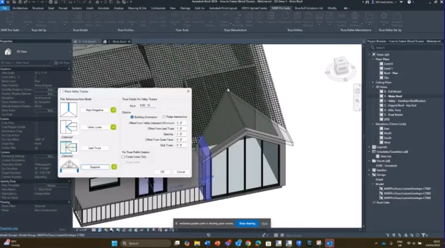
For our valley elements so for these valley trusses that we need we have tools specifically for these kind of profiles. I want to support these valley trusses on the existing envelopes for my main roof so what we can do is we can go to MWF into the truss profiles panel and we have the valley option.
So when I select valley first thing it’s going to ask me to do is select the main ridge line. So the main ridge line can be the inner edge or sorry the outer edge of the roof or the interior edge of the roof so it’s hard to see them here but you can see we have a line on the inner edge and one in the outer edge of the roof. We can choose our valley lines which are going to be the lines where the roofs intersect and again we can choose the interior line or the exterior line just make sure you’re consistent with the choice to make sure it behaves correctly so I’ll say finish.
And then if we have existing trusses we can use those existing trusses and select those as a reference to space our valley trusses away from the existing ones I don’t have any created at the moment but we could use that as an option as well and then supports we can define supporting elements if we have them in this case we do so I want to make sure I select this wall on the left and this wall on the right so these are going to be the supporting elements for this portion of the roof.
Once I’ve defined the supports I’ll hit finish and again we’re greeted by this dialog box where we can specify where the heel alignment is going to be so I’ll click OK and then on the right we have some information related to the roof we’ve selected and we’ve got some options to define how we want to place these valley trusses so building orientation what this is referring to is the offset from the boundary the outer boundary of our roof towards the building so it’s building orientation towards the building ridge intersection is based on the intersection point from where the ridge intersects and it’s taking the measurement from this point towards the boundary of the roof.
So we have two ways of defining where to place our valley trusses one from the edge of the roof towards the inner side of the roof and one from the ridge line towards the outer edge of the roof. I’m going to use the building orientation because I want it to be taken from this point and go towards the roof so I can set an offset from the valley intersection and that means when we get to this point here what is the minimum distance that we can generate a valley truss so I’m going to set this to one foot we’ve got offset from last truss if we selected the last truss option and we’ve got the spacing option where we can define the consistent spacing of the valley trusses so I want them to be two feet on center we’ve got offset from outer face again referencing that two inch offset that we have from the outer edge and you can generate stub trusses if you need to generate trusses with a shorter heel distance so you can use the stub truss option.
So I’m simply going to click OK we’re going to generate some more truss profiles as you can see and you’ll see that these are aligned to the existing line work of the roof so you can see these are going to be resting on the main roof portion there.
I also want to do this on the opposite side as well so again we can go through the process very quick so go to MWF valley choose our main ridge line and the outer edge choose any valley lines that we have select our supports and then hit finish again I’m going to simply accept the current settings and I’m going to set the offset from valley intersect to one and the spacing to two feet okay making sure I keep that outer face offset and again it’s going to generate those profiles just like it did before quite hard to see these right now so what I’m going to do is isolate the category so you can see that a little bit more clearly on how it’s placing these you can see there straight generating these envelopes in relation to the slope of the roof and that’s how we can do it.
Okay so what I’m going to do now is show you how we can edit or manipulate some of these model groups. Okay so I’m going to focus on this particular element this particular valley here. Before I do that I’m just going to remove these two trusses at the end so let me just select this one and this one and hit delete on those two. What I usually generate at the end is standard trusses not valley trusses so you’ll notice when I select these ones here these valley trusses they’ve got a type name of V002 because they’re valley trusses they’ve got the V prefix there our standard trusses usually have a CT prefix so yeah CT value there for standard trusses.
So for this part of the roof here I want to generate some standard truss elements and I’m going to go to MWF and I can use the common option as mentioned before and we can use the create option I’ll demonstrate what the common option looks like so if you click on common you’ll see that we have a few different options on how to define where we want to place these common trusses so we can choose main ridgeline which will be this one you can choose our supports and we can again define our heel placement we’ve got some read-only information here based on the roof pitch overhang length height and heel height again we can define a start and endpoint to say where we want the truss to span from and where we want it to finish and we can define the spacing so I’m going to say two feet on center and a two inch offset from the outer edge not worried about adding any additional trusses but for now I’ll click OK and it’s going to generate some trusses there.
So let’s just have a look okay so we’ve got these two trusses that we just generated and what I’ll demonstrate now is how we can make an adjustment to these trusses so I’m going to go back to this view here so okay so we’re looking at our valley our valley truss and I want to make an adjustment to the valley truss purely because of the style of this window we don’t want to see the trusses through this window so what we can do is we can make an adjustment to the truss profile that has been generated.
If I isolate this truss that I have selected you’ll see this king member that is generated in the middle if we use the create option it doesn’t generate this member and we can simply generate the truss without it.
I’m going to go into MWF and under the truss tools we have options to create scissor trusses and split cap trusses I want to create a scissor truss because I want to replicate the profile of the window so if we just show that again you can see we want to follow this kind of profile here so I’m going to select this truss our T001 truss and you’ll notice that our T001 is the same as the truss behind it they’re both T001 so any changes I make to this truss at the front is going to affect the truss at the back as well because they’re generated from a model group.
So I’m going to isolate this truss and I’m going to go to edit group before I can use the scissor truss tool or the scissor tool to generate a new profile I need to get rid of this supporting element in the middle I want to firstly delete that secondly I’m going to hit finish.
I’ve taken a measurement beforehand so I know the distance I need to offset in order to replicate the window profile so I’m going to do now is select my model group go to MWF and I’m going to click on the scissor option so when I click on the scissor option you’ll see we’ve got the option to generate or at least define a length using inches feet millimeters and we can use a range of units as well it’s reading our measurement units based on what is currently defined in the project so I’m going to set the elevation height to four inches because the height from the lower end of this truss is around four inches to where the top of the window is sorry not four inches four feet 48 inches so we can apply to all instances of the same group which means the other T001 truss envelope is also going to be affected as well so I hit OK and you’ll see here that it’s affected the profile by raising it up from the midpoint by four feet.
So now when I go to my window you’ll see that the first truss kind of hard to see is no longer let me see if I can try and take off I’ll show you in a moment guys when I’ve done the rest when I’ve done the other couple ones couple of our trusses as well.
So we can also affect these valley trusses so I’ve made a change to the original T001 trusses and I also need to it’s hard to see to honest let me do something really quickly so okay much better all right so now we can see all the other trusses which are also overhanging in this area these were generated as valley trusses but we can still make the same kind of changes again these are separate groups you’ll see that this is V002 the truss behind is V003 so and so forth so each variation of truss envelope will generate a new type.
So with V002 selected I’m going to go to edit group sorry before I go to edit group I’m going to isolate it so hi and I want to edit group again I want to make sure that this is set for me to use as a scissor truss or with the scissor truss option making sure there are no mid supports or any overlapping lines anywhere so I hit cancel go to MWF and click on the scissor option again I want to define the height of four feet and I’ll click OK.
Okay on the other occasion you may find that one of the truss profiles doesn’t want to play ball that’s okay we have ways of working with that anyway so I’ll just show you another way that we can achieve the same result just using our manual edit options so we go to edit group what I can do is copy this bottom chord using the Revit copy and I’ll copy this above its current location by four feet okay then I’m going to hit escape and I want to copy these two members here at the top and I want to bring these down so they’re in alignment with that four foot marker that was just placed now I can delete the bottom chord and I can trim the line work to make sure that the profile is consistent okay so you can see there we have our profile I’m going to use SL to split line and the trim tools just to make sure our line work is nice and tidy so now we have our truss envelope we can hit finish and I can bring back the window where we can now see that the profile is looking a lot more acceptable I guess.
All right I’m not going to bore you too much with those settings guys and making sure I change every single one but you get the idea you can modify and manipulate the profile to generate the truss envelope you need.
Okay so what I’m going to do now is focus on the hipped roof so you may have noticed we did have a hipped roof portion here as well and we can also create envelopes for those so here we have the hipped roof and just like before with the valley roof I need to define some properties related to this particular roof so first thing I’m going to do is generate some girder members which can be used as supporting elements for our hip end and other features for our trusses.
So in MWF I’m going to go to the truss profiles panel where we have the hipped drop down menu from here the first option is girder so I’m going to click on the girder option and we can select our supports so we can select the wall on the right and this wall on the left these are going to be the supporting members for the girder truss I’m going to generate I’ll hit finish and then we can choose the hip lines so I want to make sure I’m using the exterior lines so we are using these as our reference the exterior parts of the roof as the reference points what we should see here is the roof pitch so I’m going to just go back to supports just making sure it understands the supporting elements that I’m selecting.
Okay once you select supports you should always see this pop up so if you don’t then you may have to do that process again but you can see we’ve got the structural layer offset to the far side and we’re not going to add a cantilever offset all right so now we can see our roof pitch information here.
We can now define how we want to generate these truss girders we can generate multiple envelopes or we can generate a single one if we go to multiple we can choose spacing minimum height if I just want to generate a single truss girder we can select the offset from the hip intersect which is where the hip lines cross or where they meet and then we can set an offset from the outer face I may want to generate a couple so I’m going to go to multiple and we can say offset from hip intersect I’ll leave that at zero we don’t want to offset away from here I want to keep them in alignment and the minimum height not too worried about that because I might want to delete these anyway so I’m going to set this to two feet you can define the spacing if you want to space them consistently apart at two feet and define the outer offset at two inches I’ll click OK and we can see we’ve got multiple hip girders generated in these areas so the minimum height would affect how small the hip girder can be when it gets to the edge of this part of the roof I am only going to define one at the hip intersection so technically I don’t need these ones that was just to demonstrate that we can create multiple if necessary.
Okay so I’m just going to select these model groups and simply delete them.
Okay so for the main portion of the roof the main pitch we can also generate our truss envelopes using the standard tools that we’ve seen before so if I go to MWF use the create option we can define our supports on the left and right click finish and again we can choose the alignment of our heels again I’m going to keep this consistent throughout the project and I’m simply going to just quickly define these settings here I want to align to the exterior side just like I did before and I want to space my trusses two feet apart I want to keep the offset consistent at two inches and I’m not worried about an additional truss at the end.
So I definitely should have done this point at the start because now I’ve got too many envelopes but it’s okay all right so we don’t need this one this one that one okay so I believe we’ve got too many here which is not a problem because you can see that we have the main truss elements that we need there.
So for the main hipped part of the roof we can generate a hip end but we can also generate individual hip elements as well so if I extend the hip menu you’ll see we have hip and parallel jack which would affect these parts of the roof we’ve got hip which will generate the member at the hip intersection or where the hip line is and we’ve got perpendicular jack which will then create our trusses for the sloping portion of the roof here hip end is a combination of all of these options here so this is the quickest option and it’s going to be my preferred method today.
So first we need to define the hip lines just like with our valley we need to define the lines on the exterior side and we can hit finish we need to define side support one and side support two so we need to define them separately so I’m going to select my support on the left first and set my heel alignment I’m then going to select support two which is on the opposite side and again define the alignment for that because we’re looking at the hip end option we also need to specify the end support which is going to be this wall here and then finally if we’re referring to any existing trusses and we want to space our hip end trusses from the girder truss that we created earlier I want to specify that truss as well.
So on the right we’ve got some options related to spacing the minimum length of the hip end members so the parallel jack and yeah the parallel jack members and the hip end members hip truss members sorry and then we’ve got the offset from hip girder so I’ve got a girder already placed I want it to be offset by two feet offset from outer face I’ll have this set to two inches and then the minimum length we can make that one foot that’s fine.
Beneath that we have some new options so these new options will allow me to define the spacing from my hip to girder so this if I have a hip member which is going to attach to the girder how much of a gap do I need to leave to allow the member enough space to be placed without clashing with the girder so based on the thickness of our members our wood members the member thickness is around two inches so it’s a two by six member two by four two by eight so it’s two inches I need to take into consideration half of that member thickness because when we generate our truss envelopes the thickness of the member is being offset equally from the center line that we see so that model line that’s generated the thickness of the member is going to be placed either side so it’s going to be centralized that line will be centralized on our member thickness so I want to leave a one inch offset so based on the position of the member thickness we can make sure that half of that thickness is taken into consideration so we’ve got hip to girder which is related to the hip to this girder member here and then we’ve got hip to jack so when we have our hip to the jack members we can also choose the offset to these as well and then we’ve got jack to girder if we have our jack members which are attached to the girder as well so I’m going to leave a one inch offset for all of these areas and then we have a setback offset which is in relation to so we’ve got the distance from the supporting element which would be our girder but then we’ve got the setback option which is based on the individual truss members within the truss so again with the member thickness being offset from the middle of the model line the setback offset is in relation to well I’ll explain once we see in the model you’ll see it so I’ll click OK in this one and what I’m going to do is just isolate these model groups okay where you’ll see that there is a gap defined between each one there’s a one inch gap in between so this is our detail intolerance of one inch and then inside of each of these we’ll also have our setback offset as well which is an offset from the end of this member or the edge of this member to the end of the edge of this member because that is a one inch offset based on the thickness again the thickness of the member so we can also take that into consideration all depending on how you want to place your trusses.
Okay so now we’ve generated our hip end we’ve generated our valley truss and we’ve generated the main roof composition there’s one more area that I want to modify before we go into generating the truss the actual trusses so let’s imagine we’ve got our roof and we have a room a room within our roof okay so we want to generate some attic trusses what I need to do is modify the profiles in order to create an attic truss so we can go through that process and then we can see how to generate one of the truss profiles okay.
So each of these truss profiles or truss envelopes that have been generated are all the same so these are all CT003 that means any changes I make to any of these CT003 profiles is going to affect all of the profiles in the roof you may remember that I copied these profiles from start to finish along the roof so there are some areas where the profiles don’t need to be changed to a CT003 or they don’t need to be changed from that because our attic room only spans this distance we don’t need the trusses this side to be affected so what I’m going to do is select only the trusses visible in this view and I’m going to generate a new model group from them so I can go to edit type duplicate and I’m going to call these ones AT001 okay so attic truss 001 now rename them they shouldn’t affect the other trusses in the model okay so these will act independently although they are of the same group they will change consistently but they won’t affect other trusses where they don’t need to.
So now I’ve generated a new model group what I need to do now is edit the profile of the new attic truss profile here so I want to keep these walls and this ceiling as a reference so what I’m going to do is I’m going to kind of copy the line work let me just make sure I can see it from the existing truss profile so I can generate the new elements of the attic truss so I’m going to select the heels and copy those okay so I’m going to just move this one oh wrong reference it’s not a big deal I’ll change it in a second okay so we can delete that one and I want to copy my heel from this side as well so once we’ve copied those elements I’m going to extend these to the upper end of the roof so I’m going to use the extend tool we can use trim extend we can also use extend multiple elements and I want to extend these to my boundary lines here all right so now I’ve done that I also want to copy my bottom chord and I want to copy this in alignment with the ceiling so again I’m going to use my Revit copy tool and I’m going to just copy this into the right position again we can use the extend multiple elements tool if we wanted to and we can just make sure that the alignment is correct okay in those areas last thing to do now is split this bottom chord because we want to have a bottom chord on the left bottom chord on the right so I’m going to type SL for split line and simply split this bottom chord I’m going to use trim this time so I can just trim the line work so it meets nicely at the corner and we have an extra member here for some reason which I’m going to delete.
All right so now I’m going to hit finish and when we check on the profile if I just isolate those you’ll see we have our attic truss profile there okay all right okay.
So what I’m going to do now is we can look into how we can generate our framing for this attic truss so I’m going to go to MWF and we can use the create tool to generate envelopes generate profiles but we can also use the create tool to create the physical truss as well so when I hit create it’s going to take me into my presets menu this is where I can generate any settings related to the truss where I can save any configurations that I’ve used and I can use them again at a later stage.
So in the general tab this is where we can choose our units so we’ve got feet inches and sixteenths of an inch and we’ve got millimeters we can choose which type of truss we’re creating is it a floor truss or a roof truss for this example it’s a roof truss and we can define the truss orientation so the web orientation sorry are they going to be pointing upwards or are they going to be pointing downwards for the truss type this will affect the members that show in the member sizes.
So before I define this I’ll just show you what I mean if I go to member sizes you’ll see the available catalog and here we have a list of okay sorry I didn’t check this part so if I go to other for example you’ll see in member sizes it gives us a range of materials to choose from if we’re specific about the material so if we say it’s LGS you’ll only see LGS related options if you select wood you’ll see wood related options there so I’m going to specify wood we can just set a project name if we want and we can define the number of plies so if we’ve got trusses which are two ply trusses we can set it to two ply and we’ll generate trusses which are two trusses pretty much glued together as the two ply trusses there we can define the webbing so the placement for our webbing members and we’ve got the diagonal behavior so when we want to place diagonals how we’re going to define the placement of diagonals so we’ve got intention left to right which is going to generate left to right members and then we’ve got verticals only nodes will only place nodes that won’t make any sense right now but it will in a moment and then we’ve got verticals positions if we don’t want to generate any diagonal members maybe we just want to generate verticals we can say whether or not we want to generate vertical members or diagonals only so we’ve got equal intersection which will space the verticals equally throughout the space fixed width which will make sure the verticals are spaced at a consistent fixed width and then you’ve got the diagonals only which won’t place any verticals it will only place the diagonals based on your diagonal settings so I’m going to use equal intersection and we can set a top max spacing any bottom max spacing I want the top max spacing to be around three feet no particular reason but I’m just going to specify three feet for the top three feet for the bottom you can set them differently if you need to you can also incorporate any heel offsets on the left and on the right you can use a consistent heel offset for both if you need to we can have verticals positioned at different parts of our truss based on any supports any point loads that we’ve placed in the truss profile as well or truss envelope and the pitch breaks so whenever there’s a change in height and finally we’ve got the member sizes so this is where we can define the members that we want to use to generate the truss so the actual members we’re going to use for the top chord bottom chord for the diagonal members our webbing and our vertical members sorry diagonal and vertical members and then the heel members as well.
So if I wanted to specify particular members specific members to be used over and over again we can then define the member type that we want to use so I could say for example imperial families and we can create a catalog for these member sizes if you wanted to adjust anything that’s available we can click on the add option here and we can add and remove anything that we use consistently or anything that we don’t use at all so maybe I don’t use the two by three so I can say remove and maybe I want to reorder this that’s fine so I believe we can drag no we can’t okay so we can then specify these three member sizes two by six two by four two by eight okay now these are available in our pick list we can reorder the members in this list as well because this will affect which one is going to be my priority so the member at the top is going to be the main member that we’re using for our truss okay so this is going to be the default option whichever one is at the top so I want the truss to be two by six but if I wanted it to be two by eight I could select the two by eight option and say send to top in which case we’re going to be using the two by eight option now you can reorder these by using the options on the right you can delete any profiles you don’t want to use and you can disable them as well by disabling the option that’s ultimately saying you don’t want to consider this one you don’t want to use it.
If you want to use consistent member sizes across all of your truss envelopes or truss profiles then what you can do is you can copy your list and you can paste it to any one of these other members so you can paste it to your bottom chord so for example if I click on bottom chord now you’ll see it’s a different list if I go back to top chord I’m going to copy the list and I’m going to paste the list here okay and now you see the bottom chord is now matching the top chord properties there if you wanted to copy them consistently across all options you can say apply to all and that will then apply the settings to all of these member types okay we’ve got some physical options as well so if you needed to have any so you’ve got top track insertion width you’ve got options to add extra insertion thickness if you need it you’ve got a chord pitch break so when you’ve got the top of the truss you can have the two members overlap or you can have it open so I’ll say lapped and then you’ve got chord end cut which can be cut from the inside or from the outside you’ve got the option to define these things here for webbing because your webbing members might be at an angle you can add an extra length if the members are not square so if they’re not at 90 degrees you can then add extra length to these angled members and if you need extra space in between your webs you can also add an offset which will shift the spacing in between your webbing members if you’re using any braces or caps you’ve got options for those as well and wall truss sheathing options here as well if you need them we’ve got designer preferences and this is related to the interactive window which we’re about to go into and then we’ve got web on launch which will generate the web automatically and replicate identical which is going to make sure that all of the trusses of the same type are going to share the same settings so when I generate the truss for one it’s going to apply the same settings to all of the trusses of the same type again if I wanted to we could save our presets so we can use them again at a later stage so I could say save as I could call this one attic truss sorry about the angry caps lock there and we can then use this as an attic truss configuration you can create different configurations for your other truss members as well save them and then you can also export them as well so you can save the file which will save it as an XML export and then you can load it in by importing in as an XML file as well.
Okay so now we’ll jump into an interactive window strange where what should have happened is we should have our attic truss so let me just see what’s happened there what’s already new hopefully this doesn’t take too long hopefully the audio issues have been sorted I’m hoping there’s some kind of sound through the webinar okay so let’s see if we can find a view that is maybe a bit more exciting I don’t want to crash Revit that’s for sure I think I should have unchecked the replicate identical option just for today I’ll know for next time I’ll know for next time all right okay so this will take a moment and once it’s loaded we should see I’m a bit confused by the profile how it’s adjusted but we’ll go back and have a look at that one so I think at this point it can cancel and it should stop the process with the trusses that have been generated up till now okay perfect okay so Revit decided to close on me that’s okay hopefully I can get that started as soon as possible guys sorry about that these things that you can’t predict okay.
What I’ll do guys is I’ll quickly generate a new truss it’ll take a while for me to go back and do everything I’ve just shown again so I’ll just generate a new truss edit the profile quickly and then yeah we’ll see what happens almost back in business great all right all right all right okay so I’m going to open the model hopefully it can well it’s faster now for some reason or something like that but we’ll see we’ll see all right okay so I’m just going to pick a part of the roof that we can just look at quickly not too worried about replicating everything I’ve just shown but I’ll just create something really quick all right so I’m going to select this roof go to MWF make sure I’m in the truss module and I’m just going to create a simple truss yeah so I’m going to choose the supports let me actually choose a different roof I know what’s going to happen in this one okay so I’m going to choose the roof MWF hit create choose the supports just like we did before hit finish and then we can choose the alignment of the heels again again I’ll keep the options consistent with what we had previously and hit finish we’re not going to select the ceiling but we can bypass that one and I want to set the spacing for the trusses to two feet just like before we should end with three profiles one that I might have to edit but yeah we should be able to use that one so I’m going to set offset from outer face two inches okay all right so the best profile we have it’s actually the middle so I’m going to select the middle profile I’m going to go to edit group so I’m going to isolate it first edit group I’ll just remove the excess there if I wanted to generate this as an attic truss then we’ve seen the process guys I’m just going to quickly go through that now again but I’ll try and keep it as quick as I can okay so I’m going to copy this line from the left just to the center and maybe I want to copy this again the specific spacing of around and we’ll go for six feet okay and I’m going to say 12 feet all right so I’m going to copy the bottom chord and I’m also going to trim these lines so SL and we want to use this extension tool right so we’re good all right so now we’ve got our attic truss I’m going to go to MWF hit create which will take us into the create options I’m not going to bore you by explaining these again guys but what I’ll do is quickly set the sizes of the members so we’ll go to general make sure this is set to wood go to member sizes where I’m going to define the member sizes as two by six members I’m going to apply this setting to all so all of the members throughout the panel are going to be two by six they don’t have an option anyway because this is all we have right now but I’ll click okay after unchecking replicate identical all right I’ll learn my lesson all right so now I want to go into interactive window so we can see exactly what will be placed it should show us the attic truss so you can see it’s shown here and I need to define what this member is right now it seems a bit confused based on this being the original bottom chord this being the new one that we added so I want to say I can select a member so one of the manually added members and I know the code for this one is a bottom track so I’m going to type B on the keyboard and that will allow us to change this to a bottom chord if you want to know any of the shortcuts we’ve got a shortcut option here which will explain how to quickly carry out any shortcuts if you need to so I’ll say generate web and that will generate the webs on the opposite side as well and once you’re happy with the settings you can simply click OK all right all right so we’re generating some void quits which will generate the profile that we’re asking for just got a little error code here nothing to worry about okay so you can see based on the modifications made to the original truss we now have this attic truss profile if I also wanted to replicate this on other trusses I could then go into the settings and apply the same settings to the other envelopes as well.
So final model was meant to be a beautiful work of art but what we have right now is a single truss it’s kind of lonely but it’s a fitting end to the webinar I guess all right I’ll hand over to Maggie for any questions Maggie are you there thanks for attending guys hope you enjoyed the webinar see you soon.
Some of our international clients that use our software