How to Frame AutoCAD Models in Revit with Strucsoft: The Ultimate Framing Solution
Date
Duration
Speaker

Michael James
Technical Consultant
Watch the recording
What’s the webinar about?
Join us for a webinar on transforming your 2D AutoCAD workflows into dynamic 3D Revit models with ease. Discover how Strucsoft Revit framing plugin streamlines this transition, enhancing your DfMA workflows with automated framing solutions tailored for Revit. This session is ideal for structural architects, engineers, designers, drafters, offsite manufacturers, and project managers looking to simplify and speed up the move from 2D to 3D modeling. See how MWF enables seamless conversion from AutoCAD to Revit, allowing you to create detailed, constructible models faster and with greater accuracy.
What you’ll learn
- How to effectively prepare and clean up a 2D CAD (DWG) model
- Best practices for importing DWG files into Revit using Import CAD
- Techniques for building a Revit model from the imported CAD underlay
- An efficient workflow to frame the Revit model using MWF (now Strucsoft)
Read the full video transcript
Hi everyone and welcome to today’s webinar focusing on a workflow that will allow you to take a 2D CAD model into Revit and frame it using MWF (now Strucsoft). I’m using a Revit file in DWG format and have decided to keep it nice and simple with this detached house model. I’m going to take a look at how we can prepare our CAD model ready for Revit, how we can utilize the file within Revit, and then how we can frame the model using MWF (now Strucsoft). As you can see on my screen, I have a few views prepared for the 2D model; we can see we’ve got a ground floor plan, first floor plan, we’ve got the associated elevations, and then we’ve got our roof plan at the top here.
There are a couple of things I would advise or recommend that you do to prepare your file before importing it into Revit. Number one, I would clean up the file before exporting to Revit. By cleaning up the file, what I mean is we remove any excessive line work or any layers that we don’t need to reference in Revit. I have some dimensions showing here, and maybe I don’t need to see those dimensions in Revit. What I can do is I can never delete or I can turn off the layers that I don’t need to see. The next thing I’d recommend is that we separate views or any view references into one file per view reference. The reason for this is that we can import only the references that we need, and we can also place them exactly where we need to when we’re referencing the position of doors, windows, and other elements. We can place our ground floor plan on the ground floor plan level inside of Revit, and it’s important that we have a reference that we can select to make sure that the alignment is exactly as we want it.
Another thing I’d recommend is that we have a point in the model that we can use to check the scale. In this case, we have our wall framing or our wall structural layer, and I want this to be consistent with the layer that we’ll create inside of Revit, and this is a nice easy reference I can check. What I’m going to do is create a dimension in between this layer, and we can use this to check the scale at a later time just to make sure it’s correct after we import the model into Revit. As I mentioned before, when we’re separating our views, we can separate our views into their own DWG files, and this is a useful way of managing the view references. And as you can see, if I go into my folder where I’ve stored all of my views, you can see each of these views has been separated into their own separate file per view reference.
Now if we jump into Revit, we can see how we can import the DWG files in the process and how we can do that. Now inside of Revit, we want to import our CAD file. When we import our file, we’ve got a couple of options; if I go into the insert tab, you’ll see on the link panel we’ve got the option to link CAD, and on the import panel we’ve got the option to import CAD. The difference between the two is if I was to link my CAD model, that CAD model would have to maintain a relationship with the original CAD file; it could update based on any changes in the original CAD file. If I import the CAD file, then I’m importing the file at a set time, and I don’t need to maintain the relationship with the original file, which means I’ve got a bit more flexibility when it comes to manipulating the CAD file. I can explode it, I can change the way things appear inside of the file without it affecting the original file or without having to link back or refer back to the original file. What I’m going to do for today is I’m just going to use the import CAD option, and if I go to import CAD, then we can see within my folder we have our files. Here within our folder, I want to bring in the ground floor plan. I’m in level zero in my Revit model, and I want to bring in my level zero floor plan.
When I’ve selected the DWG that I want to use, I can then choose how I want to bring it into Revit. I’ve got the option of selecting the current view only, which means when I import the file and import my DWG file my reference, it will only be placed in the current view only, and I’ll only be able to view it in that view. If I leave this unchecked, it can also appear in other views, for example 3D views, elevations, and other views for example. For our layers, we can decide whether or not we want to keep the original layer colors; we can preserve the layer colors, we can invert them. If we’re working on a black background in AutoCAD for example and we’re using white lines, and now we’re working on the white background, we can invert the color of the layers—it’s just visible in both options. And then we’ve got black and white, which will convert any lines into black and white lines rather than using colors. We’ve got layers we can choose which layers to bring in; as we’ve got to bring in all light layers, or we can choose to bring in only visible, and we can also specify which layers we want to bring in. As I’ve already done the clean up in the CAD file, I don’t need to do much more in this file to make sure that it’s workable. In this case, I can select visible because the layers that I want to use are already visible.
Import units: we can select the units that we want to use; we can override the units in the file, we can use feet and inches, meters, any of these available; otherwise, we can auto detect based on the units that we were using in the original DWG file. If there are any lines that are off axis, they’re not straight, we can auto correct those lines and straighten those as they’re brought into Revit. When we’re positioning our original DWG file in relation to our Revit project, we can choose how we want to position it. We’ve got auto origin to origin, which is going to take that base point within our CAD file, and it’s going to align to the base point within the Revit file. Auto center to center will detect the extent of the file, and it will find the center point, and it will place the model at this from its center in alignment with the base point in Revit. We’ve got manual origin, in which case we can define where we want to place it, and then we’ve got manual center, which is going to take the center of the CAD file, and we can detect it, and we can decide where to place the file based on its center point. For now, we’re going to use the auto origin to origin option, and we can decide which level we want to place this file on; as we’re in level 0, and I want to place it on level 0. Orientate to view: this means it’s going to match the orientation of our view—how it currently is placed, how our view is currently orientated; it’s going to orientate to match the view. All that’s left to do now is click open, and you can see it’s going to take our origin point from our CAD file, and it’s going to match it to the origin point in our Revit file. Just to prove that, if I go tap rh just to reveal any hidden elements, you can see this is our origin point in Revit, and this matches the origin point in our CAD file. You’ll also notice when I select the CAD file that this file is pinned, and this is to prevent it from being moved accidentally, and we can also unpin this as if we need to move the file for any reason. But as we’ve placed it based on the origin point, it’s automatically dropped in the position, and it’s pinned automatically.
Now I’ve brought in the view for my ground floor; I want to bring in an elevation view as I can set up my levels. What I’m going to do is I’m going to go to my self elevation here; in our self elevation, you can see that we have our existing Revit levels, and we also have our import symbol, which is our DWG file that we’ve imported into Revit. What I want to do now is bring in the self elevation; we can see where our levels should be positioned in relation to the DWG file. What I’m going to do is go into the insert tab, I’m going to go to import CAD, and I’m going to load in my elevation self. I’m not going to change any of these properties here, but for our layers, we do have the option to set all visible or specify. Again, I’m going to set it to visible, and I’ll click open. Once our file is brought in, you can see here that elevation is slightly higher than it should be in relation to our existing level zero or our base point in the file. What I can do here is I can move the import symbol. Usually they’re pinned once they’re imported, but I can unpin it, go to move, and then just make sure that our level zero in our DWG file is aligned to our level zero in Revit. You’ll also notice that our level one is slightly higher than the level one inside of the DWG file. That’s easy to fix. We can use the align tool. If I click on the level here, I can click on the align tool, select align within the DWG file, and align my level to it. We need an additional level for our roof, and we have a couple of options. I can either copy this existing level, or I can create a new level. The quickest method is to copy this level. I’m just going to copy level one up to this roof level here. If you have line work in the DWG that you would like to reference, we also have another option. If I click on this level line or sorry, if I use the level create tool, go to architecture datum, click on level, then we have line where we can draw the level in position, or we can pick lines which will pick a reference line from the DWG file, and I can then associate this level with this selected line here. You can see there that we have a level associated with that line. We can rename the level. I want this to be roof to match what we have in our DWG, and I’ll just hit enter. As we’ve created a level with associated views, it’s asking me if I would like to rename corresponding views, in which case I will say yes. And I’ll show you exactly what we expect to see here. We’ve got our roof level, and we have a roof plan generated for our roof level or a plan view for our roof level.
As we’ve got our levels placed correctly, what we need to do now is make sure that our self elevation is lined up or positioned correctly in relation to our ground floor plan. To see this more clearly, we can go into a 3D view where we can see that our elevation is slightly out of position for our exterior walls here. There’s an easy way that we can adjust this to make sure that they’re in alignment. I’m going to go into my level zero plan. In the architecture tab, I’m going to go to the work plane panel, and I want to create a reference plane. I’m going to use this reference plane to indicate where the exterior wall should be, and the great thing about a reference plane is this also shows in elevation views such as our self elevation in this case. I’m going to click on my DWG, click move, and now I want to align this exterior wall to that reference plane. Now when we check in 3D, you can see that our walls are aligned nicely, and our doors and other elements are nicely positioned. It’s best practice to also check the scale and make sure that the scale of the imported element is correct, and what I can do to check the scale of this model is I can go to the reference point that we’ve used previously and just take a measurement just to make sure that the dimensions are consistent. If I go to the annotate tab, I can create an aligned dimension, and I can select the same references that I chose in my DWG file previously. There’s a hundred mil structural layer here, and if we go back to our DWG file, you’ll see that we have a hundred mil structural layer thickness here as well.
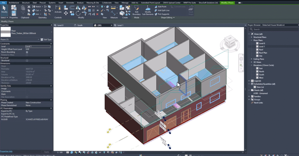
Now we’ve made sure that our DWGs and our CAD files are nicely aligned, are positioned correctly, our levels are placed as they should be. We need to place our geometry. Now we want to place our walls, we may want to place some floors and other elements as what I’m going to do here is I’m going to create a wall type to match what we have in our model. The first thing I want to do is I want to measure this wall to make sure we’re getting the same values or using the same values for our wall buildup. You can see here if I take the measurements for the structural layer and the sheathing layers, I’m just going to change the scale. I’ve got a hundred mil structural layer, and we’ve got 13 mil sheathing boards. I just want to double check that these sheathing boards are indeed 13 mil as I believe this might not be the case. Let me double check on this one. I’m going to go into my units, and I want to change the precision just to make sure it’s given me the reading. You can see here that we’ve got a hundred mil structural layer and 12 and a half mil sheathing boards. I want to create a new wall type. I’m going to go to architecture wall, and here we have a list of wall types. I want to use the wall partition with a 75 mil stud. I’m going to use this as a benchmark because it closely matches what I have here. We’ve got two sheathing layers, and we’ve got one structural layer or one stud layer. I’m going to go to edit type, and I want to duplicate this type to create my very own. I’m going to call this one interior because this is for an interior wall, and I’m going to say 100 mil stud with 12.5 mil sheathing, and I’ll click okay. And now I want to make sure that the structural layer matches what I have in the description. If I go to structure, click edit, we can see the wall composition. I have two finished layers, one on the exterior side 12.5 mil and one on the interior side again which is 12.5 mil, which is what we want. For the structural layer, I want to make sure that this is set to 100 mil to match the structural layer thickness that we have in our wall. For Revit, it’s important that we distinguish which layers are which, and for MWF (now Strucsoft), it’s also important that we have our wall set up correctly as I’ll come back to the MWF (now Strucsoft) portion shortly, but for now I’ll just make sure the wall is correct.
Now we have our own wall type, and if I wanted to generate my walls now, I can simply click to place those around the model. It’s very easy to place our walls, and we can do that fairly quickly by clicking between point a and point b. For exterior walls, I have some walls which I’ve already generated. If I go into the wall tool, you’ll see that we have exterior brick on wood stud for our ground floor, and just before we can choose how we want to place our wall. I can take the center line, and I can position my wall in relation to the center line as you can see. When we’re drawing our walls in Revit, it’s important that we draw them in a clockwise manner in order for them to be orientated correctly, but it’s very easy to adjust that if we do accidentally draw them in the wrong orientation. As well as using the drawing tools, we also have a range of pick tools that we can use as I’m just going to create this wall here, and I’ll just use the edit tools just to finish this one off. As you can see, we’ve got our walls which are placed, and it can now remove this dimension. We have another wall type here, and as you can see, it’s slightly thicker than the wall that we have positioned. What I want to do is generate another wall type to match this scenario. Again, I can select the wall that I’ve got, go to edit type, and make the adjustments there.
Once our walls have all been drawn and placed correctly, then we may need to place our floors and roofs. With floors and roofs, we can create those in a similar way to how we created our wall. If I go to the floor option, you’ll see we have our floor type, and in the type properties, we can duplicate, we can rename an existing one. But here we’ve got the floor composition, in which case we can specify the layer thicknesses. I’m going to place a very simple floor. I just want to create a ground bearing floor in this case, and I’m going to we have a couple of methods on how we can do this. Again, we can place using lines. We can use rectangles and other shapes. We have pick lines where we can pick line work in the DWG file if it’s available, or if we have existing walls in place which we do now, we can use the pick walls tool to do that. You can pick walls one by one, or if I hit tab on the keyboard, it’s going to pick all of the walls which are drained or a continuous loop. I can simply select all the walls at once, and we can choose which part of the wall we want to extend to the middle of the wall or the face of the wall. I’m just going to make this the middle of the wall in this case, and hit the tick there. Now in 3D, this is currently what we have based on what we’ve just placed in our model. It’s starting to come together, not quite there yet, but it’s starting to come together.
Now I need to make sure that the walls are referenced up to the first floor. I can select all of my walls here in my filter if I want to make sure only walls are selected. I can select walls, and then all of my walls are selected here. In my wall properties, we’ve got the walls constrained to the level zero this level here, and they want we want them to stop at the first floor. Top constraints: I want this to be up to level one; you can see there it will stop at level one in this case. Now when we look at our plan or our model, you can see there’s my walls and how they’re positioned in the model. Now I need to bring in my level one floor plan; I’m going to go to level one, I’m going to go to insert, and I want to import CAD. Here in my folder, I’ve got my level one floor plan, and I just want to bring in my DWG as is. Position wise, you can see it’s slightly out of alignment; no problem at all. What I can do is reposition it, and in order to do that, what I want to do first is turn off any lines that we don’t need. In this case, when you bring in an imported model, you can query the model which will allow you to see any line work within that model. Here I have a line which is not part of the exterior walls, but you can see it’s on the dimension layer. What I want to do is I want to hide these in view, and you can see there they’re no longer visible. We can hit escape, and now we can see just the geometry for our walls which which is what we want in this case. I’m just going to click move, and I want to move my imported view it aligns with the exterior walls on the view just beneath. I just want to choose the reference, and we can use that wall at the top corner as a reference. Again, in our 3D view, we just want to make sure that everything is aligned as we want it to be. You can see here based on our line work and our walls that this is all aligned nicely.
Again in our first floor, we can start to build up the wall composition, and if I go to architecture wall, we want to make sure that we’re positioning our walls on the first floor and that they’re ending at the roof level. And then from there, we can do what we did before by just drawing in our walls. This is my wall on the first on the first floor which is slightly different to the wall on the ground floor. Again, we just want to place the interior walls. Now once our walls are placed, we can check the 3D model again just to make sure that everything is constrained to where it should be. I can tab select these exterior walls just make sure that those are finishing up. Sorry at the roof level as we want them to. It’s slowly coming together as you can see. Now I’m going to place the floor on level 1. I’m going to go into the floor tool, and I’m going to select the timber floor, and if I go to edit type, I can duplicate it. I’m going to keep the name in very similar; you can have a 20mm chipboard, and we can have 200mm joist. I’ll click okay, and there we have a new type. I want to modify the structural layer or the chipboard layer and the structural layer just to match the name to make sure it corresponds and is consistent. I’ll click okay, and there we have our floor type. Again, I want to select the floor boundary using my walls. I’m going to use pick walls, hit tab to pick up on these areas, and then I’m going to make sure that the walls, any walls that are going up to the floor from beneath, they’re going to stop at the bottom of the floor. I can make them, I can attach them or I don’t have to attach them. But in this case, I’ll just say attach just they’re not going through the floor. Now in our 3D view, you can see that is our new floor that we’ve just generated, and the model is slowly coming together.
All that’s left to do now for the main structural elements is to place our roofs. In that case, I need to bring in my roof plan, and I just want to bring in my roof plan view. We would have a roof reference here, but we also want to see a roof reference in plan view; we know exactly where our roof should be positioned. I’m going to go to insert, import CAD, and I’m going to choose the roof plan model. I’ll click okay, and you can see it’s positioned in our model. I’m going to unpin it just I can align it correctly, and again I want to select a reference that is consistent with what we’ve used previously. It’s going to click move, and I want to reposition our model the walls are located correctly. In our roof plan, this will be the easiest view for us to see our roof level, and let me just make sure that this import symbol is on the level; I can move it to the roof level. You can see there this is where our roof plan is, and this is where we can generate our roof. If I go into my roof floor plan, this is our roof, and in the architecture tab, I can now generate a new roof by footprint. Here we want to define the boundary lines for our roof; the easiest way to do that is to click on the lines in the model. I’m going to select these lines, but just before we can also use the tab key, but we may pick up on some things which we don’t need. I’m just going to select the boundaries for the first roof on the roof level. Once I’ve selected the boundary, I need to define the areas which are going to create a slope in the roof; I just want to select the areas that I don’t want to define a slope for. In that case, this one will not define a slope, this one will not define a slope; we’ll have a slope defined here, and we don’t want to have a defining slope there. There are some portions of this roof where we want the roof to change direction; what I need to do is split this roof into smaller portions in those areas just to make sure that this can change direction accordingly. You can see there that we have another change for this one; we can define slope, and for all of these slope defining lines, I want to make sure that the angle is set to 30 degrees as it is, and for net for any areas that we want to manually set the slope, I can create a slope arrow to determine where the slope should start and where it should stop; we have some options to control how the slope is defined, and I want to use a slope of 30 degrees just to make it consistent with what we’re with the other values in the model. I’m going to make this one non-slope defining sorry this line, and I want to use some slope arrows in this case; I’m going to split lines here, and now I can move this to that midpoint there, and then I need to place some slope arrows just to define the slope of this roof in this area, and again we want it to be consistent using the slope value that matches what we have defined previously. I’m going to hit the green tick, and then we can have a look at what we’ve created far; if I go into my 3D view, then you’ll see this is our roof; it’s close but not quite what we want because in our CAD view here we have a straight roof left to in that case. I need to go back to Revit where I can make sure that we don’t define a slope on this edge; I’ll just uncheck this one, I’m going to remove this one, and I just need to use a slope arrow there instead; there we go, I want this to be 30 degrees, and there we have our roof.
I’m going to change the roof type just to one that’s not as thick; you can see here that we’ve got our roof tile, and this is our roof as you can see there’s another roof we need to generate on the first floor; again, I’m going to go into the plan view or into the top view here; I could go into my roof my level one plan view, but I wouldn’t be able to see the reference here as this is a roof plan view, and the roof plan is in 2D; I’m just going to generate it here in the 3D view. I’m going to click roof; I can set the level to level one, and then again I can pick the boundary elements; I can pick lines to define the boundary of the roof; we may want to double check that the the reference that we’re selecting is the reference that we want; I want to make sure that this is aligned to the wall the exterior wall, and again I want to make sure it’s aligned to this exterior wall here as we can use the align tool to do that; we can use the trim tool to clean up our line work, and then once finished we can then specify the areas which will define a slope. In this case, we don’t want to slope in this area; we say do not define slope, and we don’t want a slope in this area here either; we want to create a slope in the north and south directions here in this case, and I’m going to get rid of these slope defining lines as I need to do now is for any walls where I want to change or adjust the profile to match the profile of the roof; we have two options: we can use the edit profile tool in which case we can then pick the profile of the roof by using pick lines, and we can pick the roof profile and then trim our line work to match the profile of the roof, or the other option is that we can select our walls; I’m going to hit tab to select all of my walls up the first floor, and we have the attach top and base option in which case we can select the roof and attach our walls to the roof just that all that’s left to do now is to insert windows and doors, and the easiest way to place windows and doors is in our plan views.
Here I’ve got some doors, some interior doors, an exterior door, and we’ve got some windows as in architecture; you can click on the door command, and we have some door sizes which are available; if we can take a measurement just to pick up on the opening size, we want to make sure we’re getting the correct measurement there; we’ve got the 910 opening in which case I’ll use a 910 door. We want to match the door swing as shown in the plan view; we can come back and fix the alignment of the doors shortly; we can use space bar to flip the orientation of the door, and we can place these as and where you need them for our windows; we can go to the window command, and here we have a few windows that we can choose from; we want to make sure that the windows are the correct size, and we can check this we’re referring back to our CAD plan where necessary; in this case we’ve got a 910 opening; we’ll be to have another one here got a slightly wider opening there 1810; again we can flip the orientation using the space bar where necessary for easy placement, and we want to make sure we add the windows and doors on the first floor level as now all of our windows and doors are placed; we want to make sure that they’re placed in the correct locations; I need to also place the garage doors here; I need to go to door, and I’ve just loaded in the garage door here; we’ve got garage doors; we’ll have a couple of options for doors; now we’ve got all the roofs positioned, walls positioned, we’ve got majority of the windows and doors positioned as all I need to do is check the height of some of these openings just to make sure they’re consistent with what we have in our DWG; what I can see here is that we’ve got these openings which appear to be too tall; we have another window type that we can use; we’ve got an 18 9 10, and again we’ve got another 18 10 model for these windows; I need to make sure I’m taking a dimension in my self elevation for the sill height the correct sill height here the sill height in that case is 1500; let’s let these two windows and we can do things that and I believe this one will be the same; now we’ve made the adjustments that we need to make; you can see this is how we can take our AutoCAD model into Revit and start to build it up; I don’t need to see the references for the DWG anymore; what we can do is go to our visibility graphics; I can type vv on the keyboard or you can also access this via the view tab; if we go into view, you can go into visibility graphics where we can turn off any imported categories; we can uncheck show imported categories in this view, and that will just remove them, and then we can focus more on the Revit model.
Now we’ve finished with the Revit model creation, we can now make a start on the MWF (now Strucsoft) framing; the first thing we need to do when working with MWF (now Strucsoft) in a new project is we need to load data; load data allows us to bring in any MWF (now Strucsoft) components and also any markers rule sets and MWF (now Strucsoft) data that you may need for a more efficient framing; I’m going to click and load in both framing components and MWF (now Strucsoft) components, and once complete I’ll have some data that I can use related to MWF (now Strucsoft); I’m going to go into the wall module, and I’m going to start by framing my walls; the easiest way to frame our walls is to go to the associated plan view; I’m going to go to level zero first of all and make a start on framing my level zero elements; the first thing we need to do when we go to frame any of our panels is we need to load in the families that we need the size families for our walls; what I’m going to do is go to the insert tab load family which will take me to my MWF (now Strucsoft) specific families; I want to make sure I’m going to the wall framing families; you can see in this folder here we have walls framing components metric and we have MWF (now Strucsoft) standard here; within this folder we have a range of different families that we can use to help with framing, but we want to focus on the dimension lumber families the metric dimension lumber; from there we’ve got a range of options available, but I want to choose the 38 by 140 family and the 38 by 114; I’ll click and those will be loaded in to my project; just to check I’ll type bm for beam and we’ll just check that these dimension lumber families are available; we’ve got 38 by 114 38 by 114.
Now I’m going to click on one of my walls; I’m going to choose this 140 mil layer here for example this wall here, and I’m going to go to MWF (now Strucsoft) hit create; I can specify a template go to template choose the wood default template set as active hit close and create; I’m going to use the default settings in order to create my panels just to just to demonstrate how quickly we can frame using MWF (now Strucsoft) today; we have the 38 by 114 families in this panel which is absolutely fine; I’ll click okay and here you can see we have our panel; we have a range of tools that can help with placement of members; maybe in this particular section here I want to add a join marker; I can select the walls click on place join; you can see it recognizes that we have three walls in this intersection as we’re working with wood members in this case we can specify how we would want these walls to join; I’m going to choose the long main b just for this this drain; you’ll see that it positions the markers accordingly; again for this wall I’m going to go to MWF (now Strucsoft) and I can simply hit create; there is a quicker way that I can use with this these these particular wall types and what I can do is create a template for this size that we’re using; I can create a new template use the word default set as active close and create and now if I need to make my very own settings or my very own template I can go into the miscellaneous tab to change the stud spacing; I can change the family members in the general tab for example if I wanted to use the 38 by 114 families then I can specify those families in here click okay and it will apply those settings to this template; in this case we don’t have a structural layer of 114 114 mil we’ve got a structural layer of 100 mil what we can do is I can select one of these members go to edit type duplicate and I can generate a new member type for the dimensions we’ve got 38 by 114 I’m just going to make this 38 by 100 and click okay as this new family is available I can start to create my panels using this size member; I can go into the panel properties change the member size to the 38 by 100 and also in the miscellaneous tab around any openings we want to make sure that we’re using the correct size family here as and then I can click okay and the panel will adjust accordingly; now these properties that I’ve applied to this panel I can save them as a template; I’ll go back into MWF (now Strucsoft) properties template and I can say manage folder new folder webinar and within the webinar folder I can then save my new template would 100 per meter would 38 by 100 as simple as that; if I go back into my default folder we can simply move it from this location into webinar and click okay where we’ll find our webinar template I want set as active hit close and okay and now I can apply this template for my 100 mil layers where I need 100 mil thickness for the structural layers; in this particular wall I want this to be 140 mil I can go to template select the wood default set as active close and okay as you can see it’s just resized for that.
To apply these panels quickly across the project we have something called a template map within the template map I can create my very own template map I’m just going to call this one webinar tm and I’m going to add a couple of rows of data for the wall type that I have selected the 100 mil stud I want to select that Revit wall type and I want to create a second row for my 140 mil stud as and I need to create a final type for my exterior wall which is going to be or my exterior walls sorry for my exterior brick on wood stud which will both be available here you can see wall type MWF (now Strucsoft) template and the structural layer thickness for the 100 mil interior wall I want to use my template which is for a 100 mil thickness for my interior 140 I need a 140 mil of thickness we can use the default wood template for this one and the same for our exterior wall or exterior walls once we’ve mapped the template to our Revit wall types this will speed up the process of applying our panels to our walls all I need to do now is select the walls which aren’t panelized and I can simply go to MWF (now Strucsoft) and say quick create for the remaining exterior walls I want to do the same thing select the walls and again quick create this is really speeding up the process of applying all of our wall settings all of our panel settings to each of these walls as you can see our exterior walls are all labeled our members are placed according to the settings and according to our join marker as in this case I want to go into my 3D view where we can take a look at our walls just to see how the framing is placed within the walls on the ground floor you can see around our window openings our door openings our framing is placed as expected and then for the first floor we want to do the same thing I’m going to do is select all the walls on the first floor filter only my walls click okay and simply hit quick create our first floor is now framed as and if you want we can take a look at the framing on the first floor you can see that all of our walls are panelized internally and externally all that’s left to do now I’ll just bring back the roof I’m going to select my roof or the two roofs here and we can frame these using the rafter module I can go to MWF (now Strucsoft) in the trust module we have rafters and I can simply hit create and this is just to demonstrate how quickly I can frame this model in the wood settings we can choose our rafter system we can opt to framr now and I can simply hit create I can select a layer within my roof to align to and I want it to be my structural layer in this case I’ll click okay and it’s going to place my rafter members in alignment with that structural layer we can also integrate a bird’s mouth coat if we need one in this case I’m not going to do that and it’s going to panelize each face of our roof according to the settings all that’s left to do now is regenerate and now you’ll see that the frame members will be placed accordingly for our roof again I’m going to turn off or change the transparency level we can see through the roof and see the members and how they’re positioned and finally I just want to frame the floor I’m going to go to my level one floor plan I want to select the floor in this view the easiest way to do that is to select the face I should have the floor selected let me make sure I’ve got the filter select the floors and what I want to do is go to make sure that we create an opening in the floor where we need one I can say edit boundary I could also use a shaft opening if I go to my opening panel I’ve got the shaft option where I can either draw some lines or create a rectangular opening in the floor and there we have our opening within the floor again I’m going to make sure I select the floor and go to MWF (now Strucsoft) into the floor module this time or I can simply hit create to generate a wood framed floor just with our walls we can load in the families that we need but in this case I just want to simply create a framed floor I can regenerate the panel and now in our 3D view you can see we’ve got our floor we can just change the transparency level there as what I’m going to do now is change the trans sorry change the visibility graphics for our walls for our floors for our roofs we can focus more specifically on the framing elements in the view that’s just to demonstrate how we can go from AutoCAD to Revit to Revit to MWF (now Strucsoft) and have our model fully framed in no time hope you enjoyed the webinar and that’s all for me.
Some of our international clients that use our software