Automate Wood and Metal Framing with Strucsoft For Revit 2025
Date
Duration
Speaker

Steve Crow
Solutions Technical Specialist
Watch the recording
What’s the webinar about?
Ready to revolutionize your Revit framing projects?
Find out how to automate the design, coordination and fabrication of wood and metal framing with Strucsoft, a leading Revit plugin for structural engineers, architects, contractors, designers and drafters.
In this insightful session, we’ll discover the key features that will allow Revit users to automate the modeling of walls with Strucsoft’s rule-based, template driven approach.
What you’ll learn
- Prepare and configure Revit models for framing
- Create and apply framing templates for efficiency
- Automate single- and multi-layer wall framing
- Control corner joins and automate complex configurations
Read the full video transcript
Hi there folks, I’m delivering a presentation looking at automating metal and wood framing with the Strucsoft for Revit. Now we’re presenting a few of these webinars both myself and my colleagues throughout the year, and if you’d like to see what’s coming up in the future, then if you go to our website there—the web address there—it’ll take you to the calendar. Or you can scan the QR code there that will also take you to the calendar. Yes, get yourself registered, you get advised of what’s coming up, and also you can look at the recordings of the previous sessions if you want to go back and have a look at those.
A bit about me then: my name is Steve Crow and I’ve been with Grey Tech now since January 1989—it’s about 36 years with the company. My role with the company is training and support, help and implementation, customization—that kind of thing—both with AutoCAD and the flavors of Auto Architecture, and on Revit Architecture and then the Revit MEP which is mechanical, electrical, and piping. And I’ve recently taken on the Strucsoft framing software which goes hand in hand with the Revit architecture software; you can frame your models quickly and easily using Strucsoft. In my spare time—or what little spare time I seem to have—I enjoy getting out on the motorbike or paragliding. And in the DIY department, there’s always something to do around the house in the DIY department, and also beekeeper as I’ve got nine beehives in the garden at the moment. And there’s nothing I enjoy more than getting up on the hills with my lab there, hiking up the hills or the mountains—that’s up at the top of Ben Nevis in Scotland in April time, still quite a lot of snow up there in April time.
Yes, that’s the intro. Let’s dive into the presentation: framing with MWF (now Strucsoft) in Revit. I’m going to be going to be having a look at how to load in your LGS or your light gauge steel sections and your timber sections—how to load those in to be able to use them for the framing. Look at some basic framing techniques, how to frame up your Revit walls, and setting up some standard framing templates—if you create templates, make your life a lot easier. Once you’ve created your templates, you can use a tool called quick create, and then if you have multi-layer walls where you’re looking at sheathing—that’s your plasterboard and maybe with plywood sheathing that kind of thing—you can use multi-layer templates. And then on the corners, you can set up auto join markers for the corners; you can get the configuration whether it’s timber or LGS on the corners. And then what I’ll do is at the end there, I shall put up my contact details—if you have any questions, you can email me and drop me a message or whatever and get back to you with the answers. That’s the slide I’ll put up at the end of the presentation; for example, to scan or note it down there now if you wish—I’ll put it back up at the end.
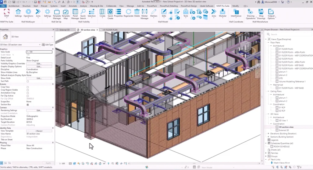
I’ve come out of the presentation there, nip into Revit here—we are Revit 2025 here with the MWF (now Strucsoft) loaded up. In my case, I’ve got the MWF (now Strucsoft) pro suite which includes the wood and the light gauge steel. Now this model here, you can see—take a look inside this Revit model—that’s one of the other views here; you can see it’s quite a comprehensive model. It’s got a heating system in there, pipe work, duct work, and that kind of thing—light fittings, the whole lot in here. You might need to coordinate with these other disciplines, and there for example you can see the ductwork is going through the wall and there’ll be a hole there in the wall which will also need framing out; you can frame around your ductwork and pipework there going through the walls. Now obviously your framing is going to be going into the walls; in order to see the framing, what we need to do there really is to set the walls to be transparent—that’s one of the first things you do is set your wall to be transparent. Now you can do it either per wall—you can with most properties in Revit—or if I go into my visibility graphics, come into here, scroll down—there’s the walls layer, set the transparency, and I’ll make it about 80 transparent—I’ll go for 60 transparent. You can see through the walls; you’ll see there now there is some framing already in here—we have a bit of a play with this; you can see in there now with the transparency turned on, you can see the framing in the walls there in some of the walls, not all of them.
Now when you receive a model, before you can start framing—because the architectural model may not have any of the MWF (now Strucsoft) configuration in there—your standard corners configurations and standard setup for MWF (now Strucsoft) and some of the defaults, the first thing you need to do before you do any framing—it’s been done here already obviously but nothing’s stopping you going to do it again—go to the settings on the MWF (now Strucsoft) tab there, look on the ribbon, go to settings and do a load data. Now this will bring in the standard framing components and your standard MWF (now Strucsoft) components and load those in, and probably come but tell me they’re already in—yes it has; look, I just didn’t apply to wall launch to override them, and he’s going to bring in the data that’s required for basic framing—it’s loading it in there, and you may have I’ve set up your own data as there we go; that’s loaded the data—we can do some basic framing. Now what I would recommend is you identify the walls that are in this project that you need to frame and draw a section of the wall outside the building; you can test the framing—the framing around openings, doors and windows and that kind of thing—don’t be don’t be when you can that it’s easier and simpler to do it on the on that spare piece of wall as it were. Let’s see what we have in here; if I hover over a wall here—look, this one here is an exterior 100 mil metal stud with panels—I select this wall in here, look up on the ribbon it comes up and there’s an option there to do a create similar; I can create a section of this wall just outside the building out the way the model itself the project—we can frame that up and see how it looks. That’s one of the internal walls; now I think there’s a thicker wall in here—if I can select it—that one there; there’s a 151 150 wall there look and again to create similar—I’ll draw a section of wall over here there we go and this external wall here as next to your brick on metal stud—select this wall and to create similar—I’ll draw a section of this wall outside here this and there we go.
Now I’ve got a section box on here—it’s chopping off the top of these walls; I’m just going to make sure that we can see your top tracks and that kind of thing—it’s nobody if you slice it off we won’t see the top tracks starting at floor one there and after the zero and I’ll set the height to go up to floor two zero offset—I put in mine is 500 I think I box there we go can I do this both at once there we go look top constraint let’s say go to floor two with the top offset of minus 500 just as I say we can see the top tracks we’ll put them in and that we can see the framing around openings such as doors and windows. I’m just going to select a window here look create similar and I’ll pop one window into there and a window into there and a window into this one as we can see how it frames around those. I’m just going to hover over a door there—click onto a door create similar and place a door into that piece that panel—I might stretch that wall a bit longer down into that panel there and I’ll put it down into the panel there—you can see how it frames around those which can make this wall a bit longer here no now you need to check your wall family to make sure it’s set up correctly for framing and to do that it’s just looking at the type properties in Revit—edit type and the construction of the wall at the top there look do an edit on that and we can see here the important thing to be watching for here is where your core boundary is and your core boundary needs to be each side of the structural layer in here—you can see that structure one metal stud layer and it’s 150 wide notice all in this particular one and we’re going to be doing going to be doing some multi-layer walls with MWF to put the sheathing on—you can see what you have on the outside on the inside of the building a 13 mil plasterboard and outside of the structure there there’s some plywood sheathing there 19 mil ply there and one is a substrate and the other one is a finish—they can be both substrates or both finishes doesn’t matter but if you have them different functions then when you come to produce these shop drawings you can say produce the finish shop drawings or produce the substrate shop drawings otherwise it’ll be all bundled together your plywood your plasterboard—you need to watch out for that.
On that one I’m not going to change on that one we may have had to move the car the the core boundary layers around if I go to look at the other one here look here you go there’s the core boundary each side of the structure this one is a 150 mil metal stud in this one that’s all good on that wall and finally this last wall here double check on this one edit type the last one is a 150 wall what’s this one and this is a 100 metal stud on that all is looking good on the Revit families. Now the next thing you need to do is to load in the stud work that you’ll be placing into these walls—this is just loading in your Revit families you would load any other family in there. Now with MWF (now Strucsoft) you get a whole library of families of studs—all sorts of setups—it’s just insert tab on the ribbon there it is load family click and it’s just any other family and the library that comes with MWF (now Strucsoft)—you have a metric and imperial library—I’m working in metric on this particular model metric library and it lists these two folders here—you have some if you generic standard parts C sections timber section that kind of thing but also manufacturers sections—if you work with a particular manufacturer using their profiles using their sections you can see in here up to Merino where for example Howick Kenco scroll down and some more Clark Dietrich there look as and there’s some FrameCAD and on yes there’s a library of manufacturers sections there and go back up one level go to MWF (now Strucsoft) standard and you can see in here there’s a whole library of if you generic standard sections you’ve got timber in there look dimension lumber I just double click onto that and it’s just loading any of the Revit family nothing different in that regard but make sure you load in the sections that you require and to frame these walls out.
Now that in this particular case I’ve loaded them all in already—I’ve got a 150 C section and a 100 mil C section I think this uses a 150 as there we go we’ve now got and the family’s loaded up the data is loaded up we can start framing now we can start framing these walls. Now there’s nothing automated has been set up as yet but if I go and select one of these walls look this is the 100 mil wall I go up to the MWF (now Strucsoft) and up here I can say create some framing on the wall model panel there create some framing create and it comes up with this dialog box here and I can just say go ahead and create and it may throw any old size in there I haven’t defined the sections that need to go in this wall as yet—it’s just going to frame up using the default options I just pan to one side you can see in there it’s got some framework in there already and in this properties dialog box this is the properties of this panel which you can nip into at any time—you don’t have to do the create button I’ve gone into here I can see in here the studs horizontal vertical in your tracks and you have a list of sections here now these were the sections that’s been loaded in you can see in there’s 100 mil section 150 and a heavy gauge 150 there and timber in there as some of the ones I loaded in earlier on some C channel in there and on in this particular case this is a 101 select the 100 section there and the same for the vertical studs and on now around the openings we get all sorts of settings on this on this tab here on the structural tab there more settings you can tweak and change in here on the miscellaneous tab this what I’m interested in is looking at the openings how is it going to frame the openings here we go do an edit there look and looking at the openings the lintel it in there for you for your doors let’s start with the windows you see around the windows again it’s a 100 mil section I can say use it for all the openings you can get to disable this top one you can set your doors and your windows to be different if maybe look at the different section there for the doors you may have a requirement of different sections on doors from windows for example but I’m just going to say on the windows there with the 100 mil on the sills and the framing I’m just going to use the same for all the openings just for simplicity’s sake in this case and then on that we’ve set the framing for the studs and the tracks we’ve set the framing for the openings I can say apply this now and it will change those sections if need be if they weren’t that initially they will be now and we can also save this away to make it easier when we’re framing later on if you click up the template tool there look it lists the templates that are in this project already and I wanted to create a new one in here for example there we go what I could do there is I could copy an existing one I go for the light gauge one there and copy and give the new one a name test the test template and it’s 100 mil stud and on that highlight that one and I can update it the current settings and if I set as active that’s the one it’s going to frame that one with it now close on that and you can see it’s got the sections in there already I can do enough color and apply and then on that I have framed that I then chose the correct section for the frame I then save other ways a template and then on that and those frame that up nicely.
I’ll zoom into here if I highlight that section there looking see that is the 100 mil section now around the windows it’s also framed them up there look you got your top tracks and bottom tracks you have full control over how it frames this in terms of the cutbacks on the cripples and the headers how many headers you have and on if you have your own configuration you can add the user default ones in the system where you can create your own configurations for the corners and such and let me just turn off these doors now I’ll go I’ll frame this one along here and if I select this one here let’s frame this one up if I say create and it will frame up if I select a template this is the 150 there it is with a lighter gauge still set as active and close and create and it goes away and frames that one with the 150 stud because that template is already created there again it comes up and says do you have a go to modify those not that’s all there the miscellaneous tab looking it’s opening framing and on the openings there look use for all openings there we go it’s 150 150 there look that’s all good close on that and this is the 150 with a lighter gauge I can say date it if I wish if there’s been a change to the settings close on that and an on that it’ll go away if there were any changes to be made to make those changes in there now if I just hide the doors with the vh visibility hide on the doors and the windows and select window there we can look at just the framing see what it’s done with the framing there we go look you can see frames are showing there this should be a 150 which it is and around the windows as you have full control of the configurations around the windows and but if these are manufactured in the factory it may be a bit awkward transporting this going to be all a bit floppy and loose with the potential if you get damaged in transit it’s not going to be very easy to lift this onto the transport you can configure the bottom tracks to say don’t split them here and they can be cut out on site if I select this panel here look I’m going to here and look at the properties on the miscellaneous you see it tracks there look there’s the bottom and top tracks edit at the moment it’s set all sorts of configurations in here look on this it’s set to split the bottom track now if I say initially don’t split it on that apply and then do an on that and you can see now when it’s manufactured in the factory the bottom track is not split it’s much safe for an easier to transport less chance of any damage from our rigid frame get it to site and if need be cut that out later on that’s in the properties of the panel there now it’s I can pick these members here and yes I can delete them but they’ll be still in the drawings database in the projects database if you you can’t just delete using the Revit delete tool if you’re going to be deleting panels what you need to be doing ideally what we need to do is use the delete tool there I’ve selected one of the members if I pick onto the delete button there look it will delete the members out of this panel and there it’s reset the sequencing friendly extraction of the length second thing member details it’s removed those members from the project as it were yes use those the correct tools to create these template maps to automate panel creation it’s on the wall setup panel in here and in there you go to the template map you can see in here you can map if you against the Revit wall type and you can apply a template one of the templates we used a moment ago where we created a template template the template is whether there’s track split how it frames around the openings the section size that was a template to help to automate the framing we can map a template to a wall type in here and that will allow us to use the quick create tool.
In here I can say add in a Revit wall and it will list the Revit walls in the project if I say there’s a block on metal stud there and then you can see that the structural layer is 200 thick and then in here I could pick the appropriate template to match up with that wall let me show you how that works I can see here for those 100 mil metal stud pad walls the interior walls I’ve used this template here and for the 150 one that I just created manually a moment ago it’s here look the 150 template I’m just doing on that what it means is now I just delete this panel here to leave the members what it means now is I could put a window across the whole drawing and then do a quick create with this button here and it would filter out all those Revit walls and frame them accordingly I’m not going to do the whole drawing because some walls haven’t got a mapping on them and it’ll kick up an error message saying cannot find a wall to apply the tank sorry cannot apply the template to apply to this wall style what I will do though I’m going to select several walls or different makeups there’s one there that’s a 150 that’s a 100 and if I can find that one there there’s a 100 I’m selecting several walls here and I picked this wall as that’s a 100. You can see I put it in the click select similar through the project and framed up 60 walls at once or whatever with those walls selected different wall families there look different wall styles come into here and using the quick create tool here click it now looks at those wall styles looks at the the MWF (now Strucsoft) template mapping and applies the appropriate MWF (now Strucsoft) template to the appropriate size Revit wall and it will frame those accordingly based on the settings in the template now you can lock the wall to the template if the template changes then it will update the wall if it’s unlocked then you can go and modify one panel to your heart’s content and there we go you can see it’s framed those walls up clear the selection and you can see in there it’s applied to that particular wall there the 100 section into this wall here automatically creates it and applied the 150 section that’s using that the template mapping there which is really useful yes now because we’ve created that mapping we can use the quick create tool as opposed to if we use the create tool we’d have to tell it which template to apply to each wall we’re going to run it now with multi-layer walls they’re a bit different because with a multi-layer wall we can apply different templates to different parts of the draw of the of the the wall again if I look at the edit wall type and look at the structure we’re looking at a moment ago there’s our structure it’s got a 150 mil structure in there I mentioned it before 30 mil plasterboard and then some sheathing there some some plywood sheathing there as I’ll cancel that we have it and do an on this or I’ll cancel on that didn’t change anything.
Up on the ribbon up on the ribbon we have a wall multi-layer panel on the left there look and it’s in here where you can set these up and to tell you what to apply to which particular layer clicking onto the settings here and this is where you set up your multi-layers and again just before it lists the walls in here that are in this project and if I just find one in here block and metal stud I think now just to show you brick where’s the block one that’s brick on metal stud block metal just to show you here we go look you can see in there you’ve got the makeup of the wall showing the left here and it shows the function as what we can do is it shows the material in here and it shows the thickness of that particular layer and here you can go and select the template to apply this is the MWF (now Strucsoft) template to apply to each of those layers here for example where it says structure metal stud layer 152 if I pick onto this and it’s a structural layer and I can say I’ll put a 150 stud in there select and there we go on that particular wall it’s going to put a 150 stud in there for your plasterboard look there’s 13 mil plasterboard and in here I can say this is not structural this is sheathing and there’s the plasterboard now I’ll show you how to create these sheathing templates in a moment that’s upon this other button up here if I select plasterboard to go in there notice it doesn’t have a thickness any of these sheathing materials pick up I don’t select on that pick up on the thickness of the Revit wall property there some plywood there look 19 mil in this one here I can say for this I’m putting some marine ply again there’s no thickness there I’ll do a select on that it’s going to put that ply in at 19 mil thick that’s how you set up the multi layers. Now to define the sheathing to define the sheathing what we can do here is go to the sheathing templates and there we are now you’ll have something to work from in there already I select this I’m going to make a new one and then copy that I can call it gypsum wallboard gypsum wallboard whoops cannot spell gypsum wallboard there we go now how are we going to place these boards what how what how what’s the joints going to be where do we start boarding is horizontal little whatever we can go and modify the way these boards are applied and here is the dialog box for setting up the boards you can set there’s the family this is just a Revit fan that’s been loaded in you can see in there got some sheathing panels and it shows with all the other families in Revit look but these just loaded in any other family would be I’ll select it here that’s the family and then you can set the how it is applied you’ve got basic vertical tiled horizontally tiled staggered joints vertically staggered joints or optimized essentially go for vertically tiled and then what about the the openings how is it going to go around the openings now again sending it to site you might not want any openings to make the structure more rigid when you’re transporting you say ignore the openings you’ll board across them the board across the openings and can be cut out on site if need be alternatively I can say break the sheathing panels at opening bounds there we go and this is now put the splits on the edges of the openings the chip is on site they’re now not having to create any l-shaped panels they won’t they won’t love you for having to create a panel this and to cut it out this you said break the sheathing and the openings you can now just read through them with the circular saw cut it down to size on site if need be yes various settings in here and the exhibit nails as I’ve not looked at the nails module yet but all sorts of secondary nail patterns in there yes that’s your sheathing do an on that and I’ll do it break at the openings on that that’s my gist of gypsum wall board set up there and you can set up as many as you want now again notice there’s no thickness set in there the thickness just to repeat what I said before the thickness is set up by the Revit wall style.
If I go back to my wall types in here and this is one we’re going to be using in a moment exterior brick or metal stud and you can see in here on the inside you have a plasterboard and then there’s a membrane the metal stud layer comes in here there’s a template that was created earlier on and then the marine ply in there as united marine plan that is setting up a multi-layer wall I don’t know on this that’s nicely set up now now we need to be using these tools in here look we have a quick create a regenerate delete in here for multi-layer walls plus a whole host of other tools in there for your multi-layer walls let’s select our multi-layer wall here come to the ribbon tab there look operations and we can do a quick create and based on the template there on the multi-layer template it’s now created a panel 10 and it’s going to frame this up and put the sheathing there as obviously a bit more work for you to do now it’s not just it’s not just studs and tracks and there we go let’s frame that up if I just if I just spins around and see my receipt on the other side there and you can see the the panels there and they’ll be split at the edges of the openings there transparent check transparency do they only do them individually I’ll send transparency up to 80. There we go on that and on that just cancel that if I tip this over a bit you can see the studs in there it’s almost this one I guess the sheathing is blocking out where you can see the studs and you can see in there look how they the paneling the plasterboard there is cut up the sides of the openings it’s going to make it much easier to install on site in that case yes you can’t see through to the to the studs there across the for the boarding yes that’s created those templates for your multi-layers and templates and also for the for these as let’s go back to another view here I’m going to go to the o1 floor plan here and again you can see the studs on the wall there and there we are and you can configure how these studs appear around the openings and on over here I’ve drawn some walls I’ve got an l-shaped intersection and a t-shaped shaped intersection here and we’re going to have a look at how you can control the joints on the corners what I’m going to do here first of all is to frame this up just with a quick create because we have a template for these walls frame these up that’s what it does quick creating those walls there it goes away selects the appropriate template for those walls and puts the stud work in there let’s see it does on the corners for now let’s see it doesn’t the corners yeah it hasn’t done a very good job with the corner has it.
Now you can go and frame those corners correctly if I select one wall there look with a control key if I select this other wall if you can find it I’ve got selected those two walls with those two walls selected I come with the ribbon here on the joins I’m putting the pull down list there I can say place a join on this corner I didn’t know I didn’t pick both walls there I’m going to put a box to it that it ignores the framing joins place a join that’s a bit easy look here we go look and it lists it’s saying how would you to join that corner and you can see they got overlapping on the corners there to make the frame more stable rigid various timber ones in there look at these there are some LGS ones various ways of configuring that corner for now I’m gonna put this one in and it’s got one two three four members in that corner there and an on that and it places that configuration on the corner if I zoom in I’ll just select the marker move down the way you can see there there’s one one two three and those four members being placed on that corner there now it may be you want to be the other orientation at the moment what it’s saying is this vertical wall here is the main wall you might want to be the other way around if I select this marker I come up to here joins and say I want the main wall I want the main wall to be this one here they will rejig the corner based on your choice there we go and it’s rejig that corner there to be facing the other way around now that was obviously a manual way of placing those placing on those goes on there I’m going to show you is how you can set you can automate this use what’s called the marker manager instead of a rule set we should delete on this delete this corner out here delete out anything in this corner here and I’m going to set up some rule sets we don’t have to mess around on every corner telling which way the main wall is what are in what to configuration put in there you’ll be all done through the marker manager up on the ribbon there’s your marker manager and in the marker manager set up your openings and things there’s all sorts of configurations in here for your openings and how walls join and different configurations here look if the if the configuration that you want is not in here you can create your own configurations for the corners and your own configurations for around the openings that thing you can come to this these are all ones that come with the program let’s have a look here at these on the join tab it lists them all in here look you can take this join here and you put into the project they can tell it how it joins these corners up and the rule set can look at the size of the wall you can take precedence the the wider wall takes present the thicker wall takes precedence of a thinner wall that makes that the main wall or you can say the longest wall is the main wall and on and in here if I drag it out a bit you’ll see you’ll see here we go for any corners it’s going to use this particular join style and if I just drag this box out a bit further you can see in there and that’s when it’s 100 mil stud with 100 millimeter stud panel you tell it the wall type the joint type and what and in here whether it’s a corner intersection these are called rule sets if I just do it on this I’ve got some rule sets in there already I have deleted the existing corners out of there and now we’re going to use the auto join it’ll be the joins are going to be determined by the size of the wall and a lot the length of the wall as to how the configuration set up on the corners the joins pull down here it is there’s the auto join tool and there’s the rule set it’s saying select the rule set you want to use I’m going to say the project panels auto join let’s select that one first cancel that it’s going through the whole the whole project sorry about that and if I go back into here yes select your walls first it’s always a good idea what was going to do trying to I don’t know how many joins are in this particular project that was close auto join that’s better project panels select and it goes away and frames them up on those joins with a particular configuration in that auto join rule set it’ll place the members on the corner and there we go if I zoom in and select the marker moves out of ways you can see what’s going on there and it’s put that style of corner in there those yes that’s using rule sets and your auto join again it’s helping to automate this process and make your life easier when you work with MWF (now Strucsoft) now all this is shown in our going through in detail in our training courses we’ll train you guys up how to set up these alternatively we can do all the configuration for you if you tell us what your company standard is for these then we can put those standards together it’s you simply case of just picking those rule sets picking those templates to frame your building up.
And yes and let me show that this one again you can get my details from there I just display settings swap there we go if you have any questions or queries there’s my email address and don’t forget if you scan the QR code there it’ll take you to our calendar of the historical events which are all recorded and stored on our website and the up and coming events as I hope you enjoyed that guys enjoy the rest of your day and thank you very much for attending.
Some of our international clients that use our software